By Central Semiconductor 120
2N3904 is a two-terminal NPN BJT made of silicon material and packaged in TO-92. In this type of transistor, most of the charge carriers are electrons, so they always have a negative charge. The state of this transistor can change from reverse bias to forward bias to conduct based on a small voltage at the base terminal (e.g. 0.7V).
2N3904 is an NPN bipolar junction transistor used in general switches and small power amplifiers. This type of NPN transistor is designed for low to medium power applications and has a medium operating speed.
The 2N3904 NPN transistor is very popular because it can be used as both an amplifier and a simple electronic switch. When used as an amplifier, its power can reach 200mA and the frequency can reach 100MHz.

Ⅰ.Specification parameters of 2N3904
•Configuration:Single
•Installation style:Through Hole
•Package/Box:TO-92
•Transistor polarity:NPN
•Frequency-jump:300MHz
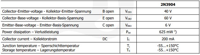
•Collector-base voltage VCBO:60 V
•Emitter-base voltage VEBO:6 V
•Collector-emitter maximum voltage VCEO:40 V
•Product Category:Bipolar Transistor-Bipolar Junction Transistor (BJT)
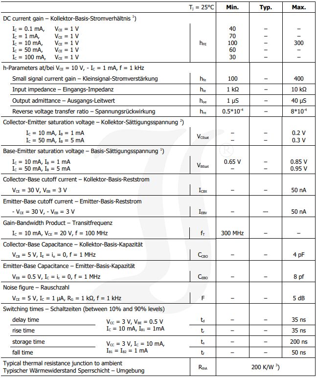
•Collector-emitter saturation voltage:300 mV
•Maximum DC collector current:200 mA
•Pd-Power dissipation:625 mW
•Gain bandwidth product fT:300 MHz
•Minimum operating temperature:-55℃
•Maximum operating temperature:+150℃
•DC current gain hFE maximum value:100
•Vce saturation voltage drop (maximum value) at different Ib and Ic:300mV @ 5mA, 50mA
•DC current gain (hFE) (minimum value) when Ic and Vce are different:100 @ 10mA, 1V
Ⅱ.Working principle of 2N3904
2N3904 consists of three areas: emitter area, base area and collector area. Under normal operating conditions, a forward bias is formed between the emitter region and the base region, and a reverse bias is formed between the base region and the collector region. When an external voltage is applied to the base, a forward bias is formed between the emitter junction and the base junction, so that current is injected from the emitter region into the base region. Since the base region is very thin, current can easily pass through the base region and then be injected into the collector region. Therefore, 2N3904 will amplify the current when working.
The structural characteristics of 2N3904 are also an important part of its working principle. First, the emitter region of 2N3904 is highly doped and has a large surface area, which facilitates current injection. Secondly, the base region of 2N3904 is thin, which helps current pass easily. Finally, the collector area of 2N3904 is large and can accommodate larger currents. These structural features make 2N3904 have good performance in amplifying current.
2N3904 is one of the key technologies of 2N3904. First of all, 2N3904 must meet the requirements of circuit design to meet the requirements for working current and working voltage. Secondly, the 2N3904 pins must be connected appropriately to ensure that their polarity is correct. When using the 2N3904, special attention should be paid to its maximum operating current and power. Do not exceed its rated value, otherwise it will cause overheating and damage. In addition, 2N3904 should also be tried not to be used at higher temperatures, otherwise it will affect the normal operation of 2N3904. When 2N3904 generates heat, appropriate heat dissipation methods such as radiators and fans should be used to ensure that the operating temperature of 2N3904 is within a safe range.
To sum up, 2N3904 is a commonly used NPN transistor, which plays a role in amplifying current in electronic circuits. Its working principle is to inject current between the emitter region and the base region through forward bias, and then inject the current through the base region into the collector region. The structural features of 2N3904 include a highly doped emitter region, a thin base region and a large collector region, which contribute to its ability to amplify current. When using the 2N3904, you need to choose the appropriate model, connect the pins correctly, pay attention to the maximum rated current and power, and take appropriate heat dissipation measures. By rationally using 2N3904, its function of amplifying current can be fully utilized to achieve the normal operation of electronic circuits.
Ⅲ.2N3904 pin configuration
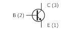
•Pin1 (Emitter): Current will flow through this terminal.
•Pin2 (Base): This pin controls the transistor bias.
•Pin3 (Collector): Current supply for the entire terminal.
IV.2N3904 application circuit
1.Amplifier circuit:
•Low frequency amplifier: 2N3904 is often used in low frequency amplifiers, especially audio amplifiers. It is a common NPN transistor with low noise, high linearity and good thermal stability. These characteristics make it very suitable for audio signal amplification. In audio amplifiers, 2N3904 is usually used as a preamplifier, responsible for amplifying the weak signal from the microphone to a sufficient size so that subsequent circuits or speakers can process or play it normally. With appropriate bias and feedback networks, the 2N3904 can provide stable amplification while avoiding distortion and other nonlinear effects
•IF amplifier: 2N3904 can also be used for signal amplification in the IF range. For example, in radio frequency (RF) transceivers, 2N3904 can be used as an intermediate frequency amplifier to amplify and filter the received RF signal for subsequent demodulation or decoding processing. In IF amplifiers, the 2N3904 is often used with appropriate matching networks and filters to provide appropriate gain and bandwidth while rejecting unwanted noise and interference. By adjusting the bias and feedback network, the amplifier's performance can be optimized to ensure signal integrity and accuracy.
2.Oscillator circuit: 2N3904 can be used to build simple oscillator circuits, such as RC oscillators. This application is useful for generating signals of specific frequencies. In the RC oscillator, the 2N3904 can be used as an amplifier to amplify the weak oscillation signal to a sufficient size so that subsequent circuits or devices can detect and process it. By adjusting the values of the resistors and capacitors, the frequency and amplitude of the oscillator can be changed, thereby producing signals of different frequencies and amplitudes.
3.Switch circuit: 2N3904 can be used as a switch to work between saturation and cut-off states, which is very useful in digital logic circuits and timer circuits. In digital logic circuits, the 2N3904 can be used as an inverter or gate circuit to convert an input signal into an output signal. By adjusting the bias voltage or current, the working state of the 2N3904 can be controlled to switch between saturation and cutoff, thereby realizing the switching function of the logic gate. In timer circuits, the 2N3904 can be used as a switch or as a component of a timer. By connecting appropriate resistors and capacitors, an RC circuit can be formed to utilize the switching characteristics of 2N3904 to realize the switching control or timing function of the timer.
4.Pulse generator: 2N3904 can be used to design pulse generator circuits. In some electronic applications, it is necessary to generate pulse signals, such as clock signals. By using the 2N3904 and other appropriate components, a pulse generator circuit can be designed to generate accurate and stable pulse signals. In pulse generator circuits, 2N3904 is usually used as a switch or flip-flop. Through appropriate control signals, the switch state switching of 2N3904 can be triggered, thereby generating a pulse signal. At the same time, the frequency, amplitude and duty cycle of the pulse can also be controlled by adjusting the parameters of the circuit, such as the values of resistors and capacitors.
5.Temperature sensor: The temperature sensitive characteristic of 2N3904 can be used to design a temperature sensor circuit. The transistor parameters of 2N3904 will change as the temperature changes, so this characteristic can be used to measure the ambient temperature. In temperature sensor circuits, 2N3904 is usually used together with appropriate resistors and capacitors to form an amplifier or comparator circuit. By adjusting the parameters of the circuit, the output voltage or current of the 2N3904 can be made proportional to the temperature. In this way, by measuring the output voltage or current of 2N3904, you can indirectly obtain information about the ambient temperature.
6.Power regulator: 2N3904 can be used in power regulator circuits to stabilize power output and suppress noise. In power regulator circuits, 2N3904 is usually used together with appropriate components such as resistors, capacitors, and diodes to achieve stable output and noise suppression of the power supply. By adjusting the parameters of the circuit, the output voltage or current of the 2N3904 can be in a certain proportional relationship with the input voltage or current, thereby realizing the regulation and control of the power supply. In a power regulator circuit, the 2N3904 functions like a voltage or current amplifier, amplifying the input signal and stabilizing the output while suppressing noise and interference. This kind of circuit can be used in various electronic equipment and systems to provide stable output for the power supply and reduce interference to other circuits.
7.LED driver: 2N3904 can be used to design LED driver circuits. By adjusting the current flowing through the LED, the brightness of the LED can be controlled. In LED driving circuits, 2N3904 is usually used as a current controller. Used in conjunction with the appropriate resistors, the 2N3904 is able to adjust the current to the appropriate level to drive the LED. By changing the value of the resistor, the current flowing through the LED can be changed, thereby adjusting the brightness of the LED. It should be noted that the current of the LED cannot exceed its rating, otherwise the LED may be damaged. Therefore, when designing an LED drive circuit, it is necessary to carefully select the appropriate resistor value to ensure that the current flowing through the LED is within a safe range.
Ⅴ.Maximum Ratings of 2N3904
Ⅵ.Characteristics of 2N3904
Ⅶ.How to use 2N3904
•2N3904 can be used in any electronic application that matches its electrical characteristics, assuming you want to switch loads in electronic applications that require currents below 200mA, then this transistor will work very well, you can use this transistor to drive various loads such as relays, large Power transistors, LEDs, parts of electronic circuits, etc.
•When used as an amplifier, it can be used in audio amplification stages, amplifiers for driving small speakers, audio preamplifiers, or in the amplification stage in RF applications.
Ⅷ.How to correctly select the working point of 2N3904
1.Clarify the design goals: Before selecting the operating point, clarify the design goals of the amplifier circuit. Determine the required amplification, output level range, and other performance requirements.
2.Determine the load line: Determine the ideal DC operating point by analyzing the load line, that is, the load of the input and output characteristic curve. This usually involves selecting a suitable current and voltage point on the load line.
3.Choose a stable working point: Choose a stable working point so that the working point can remain within the appropriate range despite temperature and manufacturing differences. Generally, choosing an operating point near the center of the load line is a good starting point.
4.Calculate resistor values: Using the DC load line information, calculate the required base current (IB), collector current (IC), and base-emitter voltage (VBE). These parameters will help select appropriate bias resistor values.
5.Select resistor values: Choose appropriate base resistor (RB) and emitter resistor (RE) to achieve the required current and voltage. These two resistors have an impact on the stability and gain of the operating point.
6.Consider the load: If there is an output load, be sure to consider the impact of the load on the circuit. This may require further adjustment of the resistor value to meet the load requirements.
7.Simulation and adjustment: Use circuit simulation tools, such as SPICE simulator, to simulate the circuit. By adjusting resistor values and other parameters, the operating point remains stable under various conditions.
8.Temperature effect: Consider the effect of temperature on 2N3904. When selecting the operating point, ensure that the circuit performance is stable within the operating temperature range.
Frequently Asked Questions
1.Are there any other transistor models that can replace 2N3904?
Alternative models of 2N3904 are: 2N2222, PN2222A, BC547, 2N4401, BC338, C945
2.What is the function of 2N3904?
The 2N3904 is a common NPN bipolar junction transistor used in general-purpose low-power amplification or switching applications. It is designed for low current and power, medium voltage, and can operate at moderately high speeds.
3.How to optimize the performance of 2N3904 to meet the needs of specific applications?
The operating point of the 2N3904 can be adjusted by selecting appropriate resistor values to achieve the desired current and voltage. This helps maximize the linear range of the transistor and maximizes the gain of the amplifier. Introducing negative feedback can improve the stability and linearity of the amplifier circuit. Negative feedback circuits can reduce nonlinear distortion, improve frequency response, and improve the input and output impedance matching of the circuit.
4.When using 2N3904, are there any circuit design issues that require special attention?
Some electrical performance parameters of 2N3904 are affected by temperature. In environments with high temperatures or large temperature changes, taking these effects into account may require measures to counteract temperature-induced changes. Make sure the supply voltage is within the specifications of the 2N3904 and avoid overvoltage. Exceeding the specified maximum supply voltage may cause device damage.