By Microchip Technology 102
PIC24FJ32GA002-I/SO is a 16-bit Flash microcontroller produced by Microchip. PIC24FJ32GA002-I/SO has 2 I2C channels, 1 PWM unit, 16-bit PWM resolution, 5 PWM channels, 8kB RAM, 2 SPI channels, 2 UART channels. Its typical operating power supply voltage is 2-3.6V, the timer resolution is 16 bits, and it has 5 timers. In addition, it also has peripheral functions such as undervoltage detection/reset, LVD, POR, PWM, and WDT.

Ⅰ.Specification parameters of PIC24FJ32GA002-I/SO
•Number of pins:28
•Core:PIC24F
•Products:MCUs
•Humidity Sensitivity:Yes
•Height:2.31 mm
•Length:17.87 mm
•Width:7.49 mm
•Qualification:AEC-Q100
•Processor family:PIC24
•ADC resolution:10 bit
•Supply voltage-Minimum:2 V
•Supply voltage-Max:3.6 V
•Data RAM size:8 kB
•Package/Case:SOIC-28
•RAM size:8K x 8
•Analog-to-digital conversion number (ADC):1
•Installation type:surface mount type
•Data Ram type:SRAM
•Installation style:SMD/SMT
•Data bus width:16 bit
•Minimum operating temperature:-40℃
•Maximum operating temperature:+85℃
•Program memory size:32 kB
•Maximum clock frequency:32 MHz
•Number of inputs/outputs:21 Input
•Number of input/output terminals:21I/O
•Data converter:A/D10x10b
•Installation method:Surface Mount
•Power supply voltage (DC):2.00V (min)
•Number of ADC channels:10 Channel
•Number of timers/counters:5 Timer
•Product category:16-bit microcontroller-MCU
•Interface type:I2C, JTAG, SPI, UART
•Product type:16-bit Microcontrollers-MCU
Ⅱ.Working principle of PIC24FJ32GA002-I/SO
1.Clock system:
•Divider: The divider may be configured to generate the required clock frequency.
•Clock source selection: Configure the clock source, which can be an internal oscillator or an external crystal oscillator.
2.Central processing unit (CPU):
•Instruction Execution: The CPU executes instructions stored in program memory.
•Register Operations: Use registers to perform arithmetic, logical, and bitwise operations.
3.Memory system:
•Program memory: Flash memory that stores user programs.
•Data Memory: RAM is used to store variables and temporary data.
4.Input/output (I/O):
•Interrupts: Configure and use interrupts to respond to external events.
•I/O pin configuration: Configure the working mode of I/O pins, such as input, output, analog input, etc.
5.Peripheral configuration and control:
•Timers and Counters: Configure and use timers and counters for time measurement and generating timed triggers.
•Serial communication interfaces (UART, SPI, I2C, etc.): Configure and use these interfaces to communicate with other devices.
Analog input/output: Configure and use analog pins, ADC (analog-to-digital converter), etc., for input and output of analog signals.
6.Power management:
•Low power mode: Configure and use low power mode to reduce power consumption.
7.Debugging and Simulation:
•Debugging function: Use debugging tools for real-time debugging, single-step execution and other operations.
8.Interrupt system:
•Interrupt vector table: Configure the interrupt vector table and define the interrupt service routine.
•Interrupt Priority: Set the priority of the interrupt to determine the relative priority of the interrupt.
Ⅲ.Application fields of PIC24FJ32GA002-I/SO
•PLC
•Sensor interface
•Actuator control
•Smart Meter
•motor control
•Environmental monitoring
•Smart home
•Vehicle communication system
•Solar inverters
•Energy metering
•Embedded controller
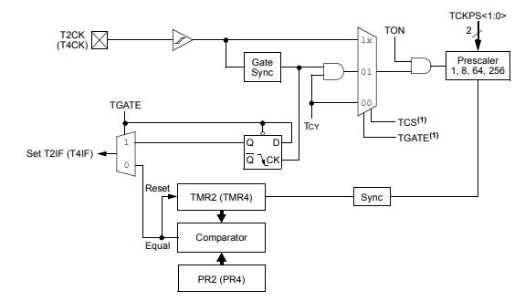
Ⅳ.BLOCK DIAGRAM of PIC24FJ32GA002-I/SO
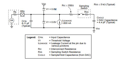
Ⅴ.10-BIT A/D CONVERTER ANALOG INPUT MODEL
Ⅵ.How to choose the appropriate power supply and grounding for PIC24FJ32GA002-I/SO?
1.Supply voltage: Make sure to provide the appropriate supply voltage to the PIC24FJ32GA002-I/SO. Typically, microcontrollers need to operate within a specified supply voltage range to ensure proper operation.
2.Power supply stability: Ensure the stability of the power supply to prevent power supply noise and fluctuations from adversely affecting the microcontroller. Power supply filtering circuits and voltage regulators can be used to maintain a stable power supply.
3.Power supply current: Understand the power supply current requirements of PIC24FJ32GA002-I/SO in different operating modes. This is critical for selecting the appropriate power supply and power regulator.
4.Power supply type: Determine the type of power supply used, such as direct current (DC) or battery-powered. Choose the appropriate power supply type according to different application requirements.
5.Decoupling capacitors: Place sufficient decoupling capacitors near the power pins to provide stable power and help suppress high-frequency noise.
6.Grounding: Good grounding is a key factor in ensuring system stability and signal integrity. Make sure there is enough ground plane to avoid common ground and signal return problems. Minimize the resistance of the ground loop.
7.Protection circuit: Add appropriate protection circuits, such as power supply overvoltage protection, overcurrent protection, etc., to prevent accidental damage to the microcontroller.
Ⅶ.Alternative model of PIC24FJ32GA002-I/SO
•PIC24FJ32GA002-I/SP
•PIC24FJ32GA002-I/SS
•PIC24FJ32GA002-I/ML
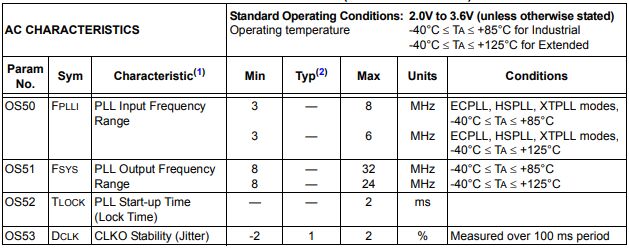
Ⅷ.PLL CLOCK TIMING SPECIFICATIONS(VDD=2.0V TO 3.6V)
Frequently Asked Questions
1.What are the advantages of PIC24FJ32GA002-I/SO?
High performance, high reliability and stability, rich peripheral interfaces, multiple peripheral functions and other advantages.
2.What is the main processor architecture used in the PIC24FJ32GA002-I/SO?
The PIC24FJ32GA002-I/SO utilizes a 16-bit processor architecture. Specifically, it follows the Harvard architecture, which means it has separate program memory (Flash memory) and data memory (RAM).
3.What are the common low-power modes of PIC24FJ32GA002-I/SO?
The common low-power modes of PIC24FJ32GA002-I/SO are: Sleep mode, Idle mode, Deep Sleep mode, and Deep Sleep mode