By Texas Instruments 136
LM393P is a dual comparator chip. It is mainly used for comparison functions in electronic circuits. It can compare two input voltages and output the corresponding logic level (high level or low level) to represent the difference between them. Relationship. LM393P is commonly used in voltage detection, signal processing, voltage comparison, switch control and other applications.
The LM393P has two independent comparators, each comparator has a non-inverting input terminal and an inverting input terminal, and an output terminal. When the input voltage meets certain conditions, the output will switch according to the relative magnitude of the input voltage. It is designed to operate from a single supply over a wide voltage range and features an open collector output, low power consumption and a wide supply voltage range. It is widely used in various circuit applications such as voltage monitoring, signal processing, and switch control.

Ⅰ.Specification parameters of LM393P
•Number of circuits:2
•Number of channels:2
•Number of pins:8
•Height:4.57 mm
•Length:9.81 mm
•Width:6.35 mm
•Supply current:1
•Package:Tube
•Reference voltage:No
•Response time:1.3us
•Supply voltage-Minimum:2 V
•Supply voltage-Maximum:30 V
•Product type:Analog comparator
•Input type:Differential
•Package/Case:PDIP-8
•Number of channels:2 Channel
•Output type:CMOS, TTL
•Ios-input bias current:50 nA
•Minimum dual supply voltage:1 V
•Maximum dual supply voltage:+/-18 V
•Minimum operating temperature:0℃
•Maximum operating temperature:+70℃
•Comparator type:Differential
•Operating power supply current:2.5 mA
•Ib-input bias current:50 nA
•Vos-input bias voltage:5 mV
•Subcategory:Amplifier ICs
•Power supply type:Single, Dual
•Installation style:Through Hole
•Current-output (typ.):20mA
•Current-Quiescent (maximum):2.5mA
•Voltage gain dB:106.02 dB
•Operating power supply voltage:2V to 30V
•Type:Differential Comparator
•Voltage-input compensation (max):5mV @ 30V
•Current-Input Bias (max):0.25µA @ 5V
•Dual power supply voltage:+/-3V, +/-5V, +/-9V, +/-12V, +/-15V
Ⅱ.Common applications of LM393P
1.Voltage detection and comparison: LM393P can be used to monitor and compare different voltages in circuits, such as battery voltage monitoring, power supply voltage monitoring, etc.
•Voltage monitoring: In many applications, we need to monitor whether the voltage in the circuit is within a safe range. For example, in battery-powered applications, we need to ensure that the voltage of the battery is not too high or too low, which may damage the battery or cause device failure. The comparator of LM393P can be used to compare the actual voltage with the preset threshold voltage to determine whether the voltage is within a safe range.
•Power supply voltage monitoring: In many electronic devices, the quality of the power supply voltage directly affects the performance and stability of the device. Using the LM393P, we can monitor whether the power supply voltage is stable, or issue a warning or take appropriate measures when the voltage is too high or too low.
•Voltage comparison: The LM393P comparator can be used to compare two voltage signals. This is useful in circuits where decisions need to be made based on the comparison of two different voltage sources.
2.Voltage comparator: LM393P is often used as a voltage comparator to compare the magnitude of two input voltages and control the operation of other circuits or devices based on the comparison results. In the LM393P, when one input voltage is higher than the other, the output corresponding to the higher input is activated (set high), and the other output goes back to low. In addition, this comparator has a fast response time, making it particularly suitable for real-time monitoring and fast control applications.
3.Sensor interface: In the sensor interface circuit, LM393P can be used to compare and process sensor signals to implement various sensor applications, such as temperature sensors, light sensors, etc. For example, in a temperature sensor, a thermistor changes its resistance as temperature changes, producing a temperature-dependent voltage signal. The comparator of LM393P can set a threshold. When the temperature change causes the voltage generated by the thermistor to exceed this threshold, the comparator will output a digital signal, which can be directly read and processed by the microcontroller.
4.Switch control: LM393P can be used to design switch control circuits to control the opening and closing of switches according to the level status of the input signal.
5.Open-loop control system: LM393P can be used to design an open-loop control system, and control the system by comparing the input signal and the reference signal. An open-loop control system refers to a system without feedback links. The output of the system is only related to the input signal and has nothing to do with the impact of the output on the system. In an open-loop control system, the LM393P comparator is used to compare the input signal and the reference signal. When the input signal is higher than the reference signal, the comparator outputs a high level; when the input signal is lower than the reference signal, the comparator outputs a low level.
6.Analog signal processing: LM393P can be used in analog signal processing circuits, such as filters, amplifiers, etc.
•Filter: In a filter design, the LM393P's comparator can be used as a switch, switching the signal path when a specific threshold is exceeded or dropped below. Combined with appropriate RC circuitry, this "threshold switching" behavior can be used to create a simple first-order RC filter.
•Amplifier: In amplifier design, the LM393P comparator can also be used as a gain element. By comparing the input signal to a reference voltage, the voltage changes of the small signal can be converted into digital output signals, which are then processed by a microcontroller or other digital device.
7.Voltage follower: LM393P can be used to design a voltage follower circuit to adjust the output voltage in real time according to changes in the input signal. In a voltage follower circuit, the LM393P's comparator is usually configured to follow the input signal. When the voltage of the input signal changes, the output of the comparator changes accordingly, thereby adjusting the output voltage in real time. This kind of circuit is usually used in signal processing, amplification and buffering applications. It can effectively isolate the coupling between subsequent circuits and input signals, and reduce signal distortion and noise. At the same time, the output impedance of the voltage follower is low, which can improve the signal driving capability and facilitate signal transmission and control.
8.Measuring instruments: Among various measuring instruments, LM393P can be used to compare and process input signals, such as multi-purpose testers, oscilloscopes, etc.
•Multi-purpose tester: In the multi-purpose tester, LM393P can be used to compare various input signals with preset standard values. When the input signal reaches or exceeds the standard value, the comparator outputs high level or low level, thereby triggering the corresponding test function. This comparison function can help the tester accurately determine whether the performance of the object under test meets the requirements.
•Oscilloscope: In an oscilloscope, the LM393P can be used to detect and compare various parameters of analog signals. For example, it can be used to detect signal amplitude, frequency, phase and other parameters, and convert these parameters into digital signal output. This conversion not only makes the oscilloscope's measurement results more accurate and reliable, but also allows the oscilloscope to integrate and communicate with other digital devices.
Ⅲ.Steps to use LM393P correctly
1.Power connection: LM393P usually requires external power supply. Connect the chip's power pins (Vcc and GND) to the appropriate supply voltage, making sure the supply voltage is within the chip's operating range. Typically, Vcc is connected to the positive supply (e.g. +5V) and GND is connected to ground.
2.Input signal connection: LM393P has two independent comparators, each comparator has a non-inverting input terminal (+) and an inverting input terminal (-). Connect the two input signals to be compared to the comparator inputs. Make sure the voltage range of the input signal is within the specifications of the LM393P, and pay attention to the polarity of the input signal.
3.Output signal connection: Connect the output of LM393P to other components or devices in your circuit. The operation of other parts is controlled based on the logic level of the comparator output. Please note that the output of the LM393P can be an open-drain output or a push-pull output.
4.Pin function: It is very important to understand the function of each pin of LM393P. In addition to the power supply and input and output terminals, there may be other pins such as reference voltages.
5.Stabilizer and decoupling capacitor: To provide a stable power supply to the LM393P, it is usually necessary to connect a voltage regulator and add appropriate decoupling capacitors to reduce power supply noise.
6.Testing and debugging: Always test and debug before incorporating the LM393P into your circuit. Verify that the input and output signals are connected correctly and that the comparator is working as expected.
Ⅳ.Pin configuration of LM393P
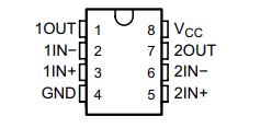
•Pin1(1OUT):Output pin of comparator 1
•Pin2(1IN–):Negative input pin of comparator 1
•Pin3(1IN+):Positive input pin of comparator 1
•Pin4(GND):Ground
•Pin5(2IN+):Positive input pin of comparator 2
•Pin6(2IN-):Negative input pin of comparator 2
•Pin7(2OUT):Output pin of comparator 2
•Pin8(VCC):Positive Supply
Ⅴ.How to realize voltage detection and control through LM393P?
1.Determine the operating mode of the comparator: LM393P has two independent comparators. You need to determine whether to use single-ended mode or differential mode. In single-ended mode, the non-inverting input of one comparator is connected to the voltage signal and the other is connected to the reference voltage; in differential mode, the inputs of the two comparators are connected to the two voltage signals respectively and their differences are compared. .
2.Provide a reference voltage: If you select single-ended mode, you need to provide a reference voltage. A voltage divider circuit, voltage regulator, or other adjustable voltage source can be used to provide the required reference voltage. Make sure the reference voltage is within the specified operating range of the chip and is stable.
3.Connect the input signal: Connect the voltage signal to be detected to the non-inverting input terminal (+) of the comparator, and connect the reference voltage to the inverting input terminal (-) of the comparator.
4.Connect the output signal: Connect the output of the comparator to the device or circuit that needs to be controlled. Controls the operation of the device based on the logic level (high or low) of the comparator output.
5.Set the threshold: The comparator's threshold voltage can be adjusted to trigger a state change in the comparator output when the input signal exceeds or falls below a specific voltage. This can usually be accomplished by adjusting the reference voltage or adding a resistor divider circuit.
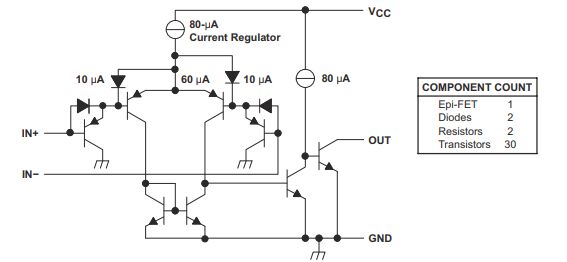
Ⅵ.Functional Block Diagram of LM393P
Ⅶ.Features of LM393P in low power consumption
1.Low dynamic power consumption: LM393P can also maintain low power consumption when the comparator switches state. Its internal circuit design keeps power consumption at a low level, which is particularly important in low-power applications that require frequent switching.
2.Low quiescent current: LM393P has very low quiescent current consumption, usually below a few microamps. This means that power consumption is kept low even when the comparator is inactive.
3.Wide operating voltage range: LM393P is able to operate within a wide operating voltage range, usually from single power supply +2V to +36V or dual power supply ±1V to ±18V. This allows it to adapt to different power supply conditions to meet the requirements of various applications.
4.High speed and performance balance: LM393P can still provide a good performance balance under low power consumption, including fast response speed and accurate comparison function. This enables efficient voltage detection and control in low-power applications.
5.Low input bias current: The input bias current of LM393P is very low, which means it can maintain low power consumption even when the input signal is connected.
Ⅷ.How to reduce the input resistance of LM393P comparator?
1.Select an appropriate input protection circuit: To prevent the comparator input from being affected by excessive voltage or current, an appropriate input protection circuit can be added. Common input protection circuits include limiting circuits and clamping circuits, which can effectively reduce the effects of over-voltage and over-current at the input end, thereby reducing the input resistance of the comparator.
2.Add a feedback resistor: Adding a feedback resistor between the input and output terminals of the comparator can reduce the input resistance. The function of the feedback resistor is to feed back part of the output signal to the input terminal, thereby enhancing the strength and stability of the input signal and reducing the input resistance.
3.Reduce the parasitic capacitance at the input terminal: The parasitic capacitance at the input terminal of the comparator will affect the input signal, causing the input resistance to increase. Therefore, reducing the parasitic capacitance at the input can reduce the input resistance of the comparator. You can reduce the parasitic capacitance at the input end by selecting appropriate pins and layout, or add a bypass capacitor near the input end to bypass the impact of parasitic capacitance on the input signal.
4.Use a differential input structure: A differential input structure can effectively reduce the input resistance of the comparator. The differential input structure refers to inputting two signals of opposite polarity into the comparator at the same time, and using the difference between the two signals as the input signal of the comparator. Since the paths and parameters of the two signals are the same, the difference between them is only related to the input signal and is not affected by other factors, thus reducing the input resistance of the comparator.
Frequently Asked Questions
1.What role does hysteresis play in the LM393P comparator?
Hysteresis plays a role in suppressing unstable flipping of the output and reducing the impact of noise on comparator performance. Hysteresis can be achieved through a feedback network, a common way is to connect a resistor and a capacitor through positive feedback.
2.What are the output states of the LM393P comparator?
There are two output states of the LM393P comparator: high level and low level.
3.What are the alternative models of LM393P?
Alternative models of LM393P are: LM393, TL331, LM2903, LM311, LM339.