By Analog Devices Inc 70
ADI’s ADRF5024, ADRF5025, ADRF5026, and ADRF5027 are reflective single-pole double-throw (SPDT) switches. The ADRF5024 operates from 100 MHz to 44 GHz with better than 1.7 dB of insertion loss and 35 dB of isolation whereas the ADRF5025 operates from 9 kHz to 44 GHz with better than 1.6 dB of insertion loss and 35 dB of isolation. Both switches have a radio frequency (RF) input power handling capability of 27 dBm for both the through path and hot switching.
The ADRF5026 operates from 100 MHz to 44 GHz with better than 3.8 dB of insertion loss and 45 dB of isolation. The ADRF5026 features an all off control, where both RF ports are in an isolation state. The ADRF5027 operates from 9 kHz to 44 GHz with better than 3.8 dB of insertion loss and 43 dB of isolation. The ADRF5027 features an all off control, where both RF ports are in an isolation state. The ADRF5026 andADRF5028 both have a nonreflective design, and both RF ports are internally terminated to 50 Ω.
The ADRF5024, ADRF5025, ADRF5026, and ADRF5027 draws a low current of 14 μA on the positive supply of +3.3 V and 120 μA on a negative supply of -3.3 V. The device employs complementary metal-oxide semiconductor (CMOS)-/low voltage transistor-to-transistor logic (LVTTL)-compatible controls.
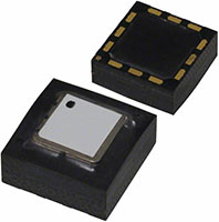
The switches’ RF ports are designed to match a characteristic impedance of 50 Ω. For ultrawideband products, impedance matching on the RF transmission lines can further optimize high-frequency insertion loss and return loss characteristics. These switches come in a 2.25 mm × 2.25 mm, 12-pin land grid array (LGA) package and can operate from -40°C to +105°C. The ADRF5024, ADRF5025, ADRF5026, and ADRF5027 are ideal for radios, scanners, and test and measurement equipment.