2001-2012 Microchip Technology Inc. DS21444D-page 1
TC642
Features
• Temperature Proportional Fan Speed for Acoustic
Control and Longer Fan Life
• Efficient PWM Fan Drive
• 3.0V to 5.5V Supply Range:
- Fan Voltage Independent of TC642
Supply Voltage
- Supports any Fan Voltage
• FanSense™
Fault Detection Circuits Protect
Against Fan Failure and Aid System Testing
• Shutdown Mode for "Green" Systems
• Supports Low Cost NTC/PTC Thermistors
• Space Saving 8-Pin MSOP Package
• Over-temperature Indication
Applications
• Power Supplies
• Personal Computers
•File Servers
• Telecom Equipment
• UPSs, Power Amps, etc.
• General Purpose Fan Speed Control
Available Tools
• Fan Controller Demonstration Board (TC642DEMO)
• Fan Controller Evaluation Kit (TC642EV)
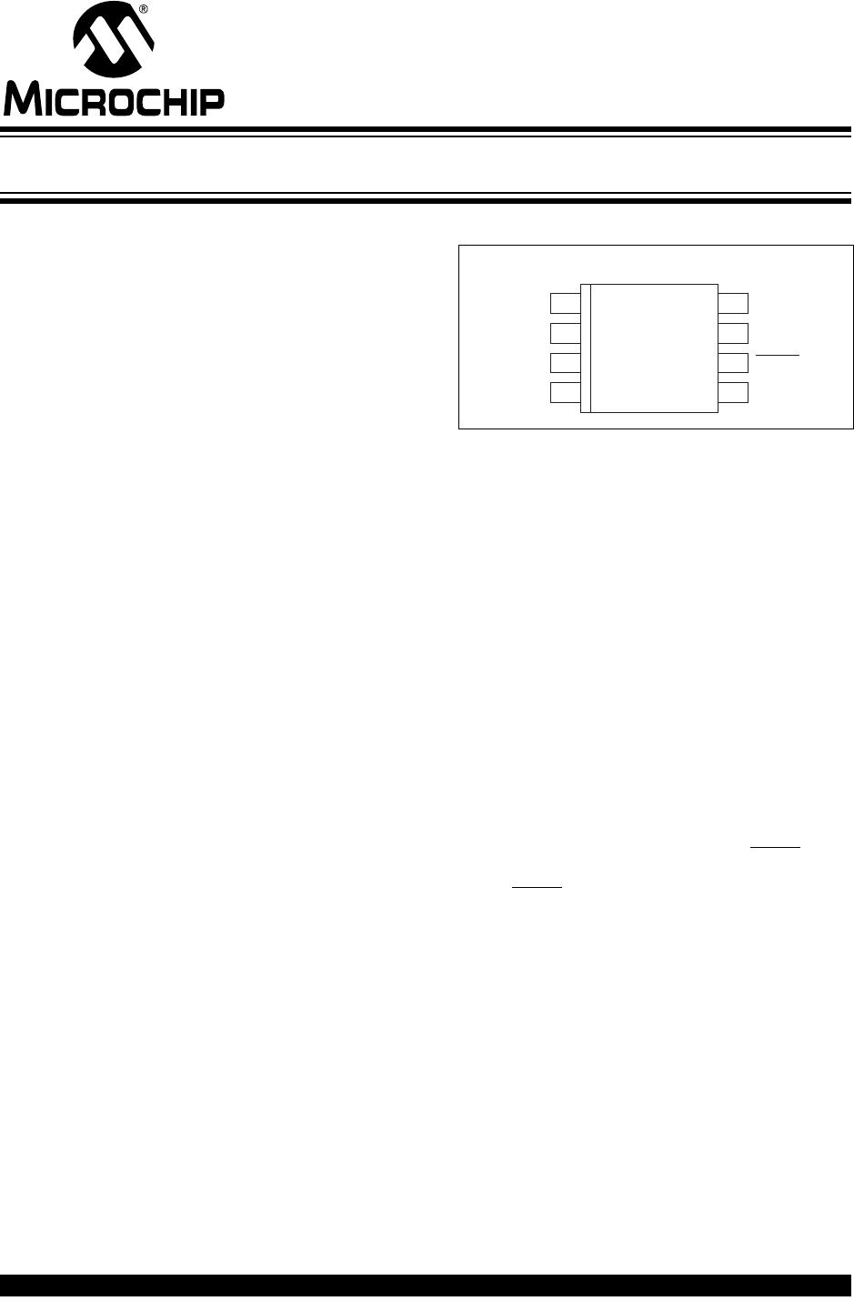
Package Types
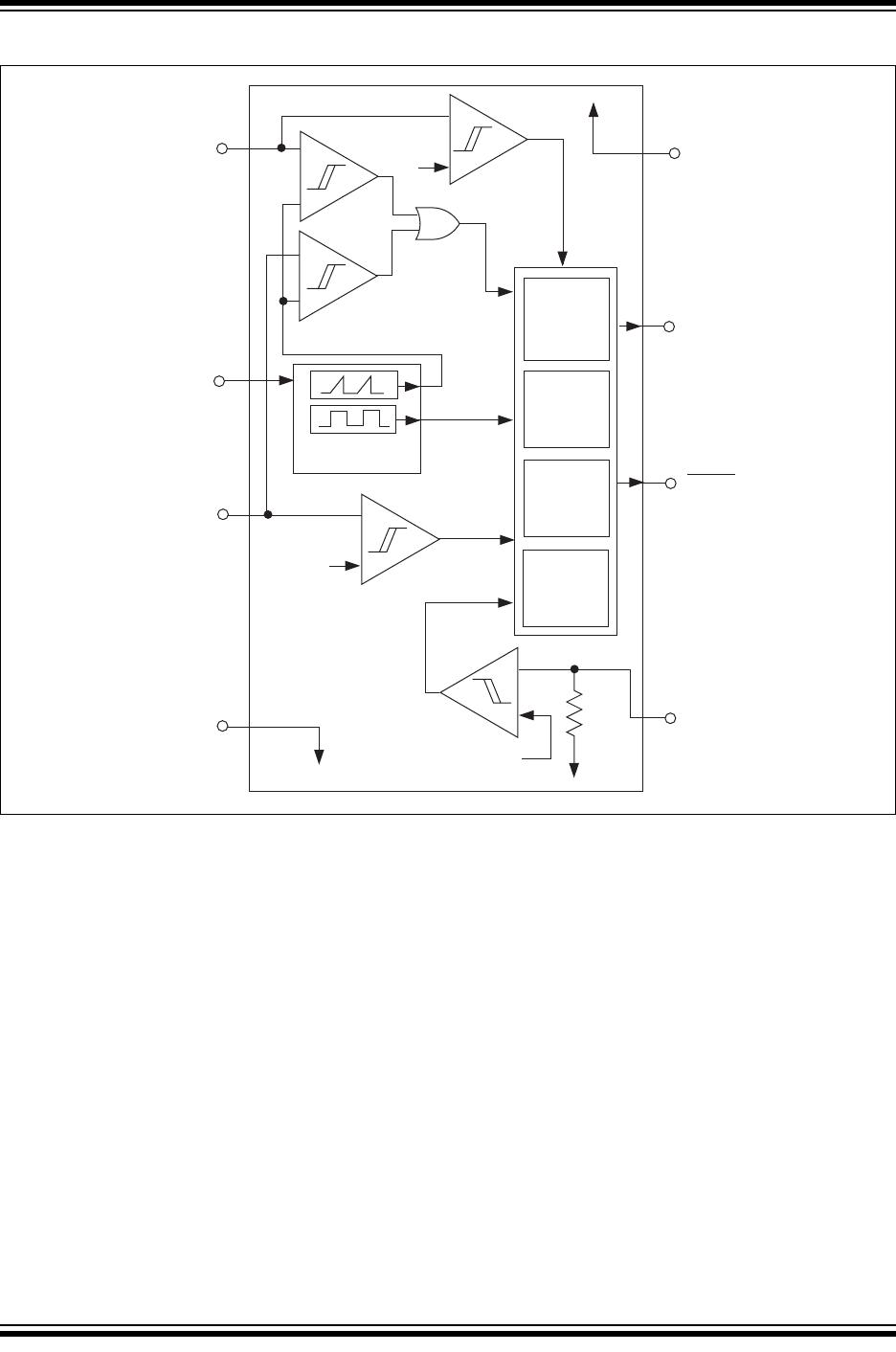
General Description
The TC642 is a switch mode fan speed controller for
use with brushless DC fans. Temperature proportional
speed control is accomplished using pulse width mod-
ulation (PWM). A thermistor (or other voltage output
temperature sensor) connected to the V
IN
input fur-
nishes the required control voltage of 1.25V to 2.65V
(typical) for 0% to 100% PWM duty cycle. Minimum fan
speed is set by a simple resistor divider on the V
MIN
input. An integrated Start-up Timer ensures reliable
motor start-up at turn-on, coming out of shutdown
mode or following a transient fault. A logic low applied
to V
MIN
(Pin 3) causes fan shutdown.
The TC642 also features Microchip Technology's pro-
prietary FanSense™ technology for increasing system
reliability. In normal fan operation, a pulse train is pres-
ent at SENSE (Pin 5). A missing pulse detector moni-
tors this pin during fan operation. A stalled, open or
unconnected fan causes the TC642 to trigger its Start-
up Timer once. If the fault persists, the FAULT
output
goes low and the device is latched in its shutdown
mode. FAULT is also asserted if the PWM reaches
100% duty cycle, indicating a possible thermal runaway
situation, although the fan continues to run. See
Section 5.0, “Typical Applications”, for more
information and system design guidelines.
The TC642 is available in the standard 8-pin plastic
DIP, SOIC and MSOP packages and is available in the
commercial, extended commercial and industrial
temperature ranges.
18
27
36
45
TC642
GND
C
F
V
IN
V
MIN FAULT
SENSE
V
DD
V
OUT
PWM Fan Speed Controller with FanSense
™
Technology