10
LT1684
The component selections for the active tracking supply
lowpass MFB filter configuration follow the relations:
C
2
= mC
1
m 1 / [4Q
2
(1+|H
O
|)]
R
2
= 1± [1–4mQ
2
(1+|H
O
|)]
1/2
2ω
n
C
1
mQ
R
1
= R
2
/ |H
O
|
R
3
=1
ω
n
2
C
1
2
R
2
m
Example:
Conditions: Output ring tone peak voltage = 100V
Ring frequency = 20Hz
Input duty cycle range = 10% to 90%
Filter Q = 0.707
Set: f
n
= ω
n
/ 2π = 100Hz
Choose: C
1
= 1.0
µ
F (a convenient value)
Then: m [4(0.7)
2
(1+100)]
–1
.005
C
2
= mC
1
C2 = 4700pF
(sets m = 0.0047)
R
2
= 1± [1– 4(0.0047)(0.707)
2
(101)]
1/2
(4π100)(1e–6)(.0047)(0.707)
R
2
= 300k
R
1
= 300k/100
R
1
= 3.0k
R
3
= [(2π100)
2
(1e–6)
2
(300k)(0.0047)]
–1
R
3
= 2k
This filter configuration yields a DC Gain of 100, a corner
frequency of just under 100Hz with gain reduction of only
0.1% at 20Hz, and a 10kHz carrier rejection of greater than
40dB at the output.
Active Tracking Supply Components
Given the previous discussion, implementation of an
active tracking supply system may seem almost trivial.
Active Tracking Supply Lowpass Multiple
Feedback Filter Transfer Characteristic (A
V
vs f
n
)
However, bootstrapping an amplifier system about its
own output creates a complex myriad of inherent stability
and response issues. Attempting such a configuration
with generic “jelly-bean” components is not recommended
for the faint of heart or type-A personalities. The LT1684,
however, makes for a simplistic approach to active track-
ing component selection.
The high voltage MOSFET transistors used in the circuit
must have an operating V
DS
specified at greater than the
corresponding high voltage supply rail plus the opposite
maximum excursion of the output signal. For example, if
a system is designed with a 240V supply (+120V,
–120V) and outputs a ring signal that has a 100V peak
amplitude, the MOSFET V
DS
ratings must be greater than
240/2 + 100 = 220V.
Active Filter Tuned Oscillator—
No PWM Input Required
A simple yet effective method of producing a high quality
sine wave is to place a high-Q bandpass filter and a hard
limited gain element in a positive feedback loop. This
circuit will oscillate at the bandpass frequency, producing
a sine wave at the filter output. The product of the funda-
mental component of the limiter and the filter gain at the
bandpass frequency determines the output amplitude.
This type of circuit is commonly referred to as an active
filter tuned oscillator.
HERTZ (Hz)
1 10 100 1K 10K 100K
FILTER GAIN (dB)
1684 F02
–50
0
50
APPLICATIO S I FOR ATIO
WUUU
11
LT1684
+
R
F3
R
F1
+
R
F2
V
IN
C
F2
C
F1
V
OUT
1684 F4a
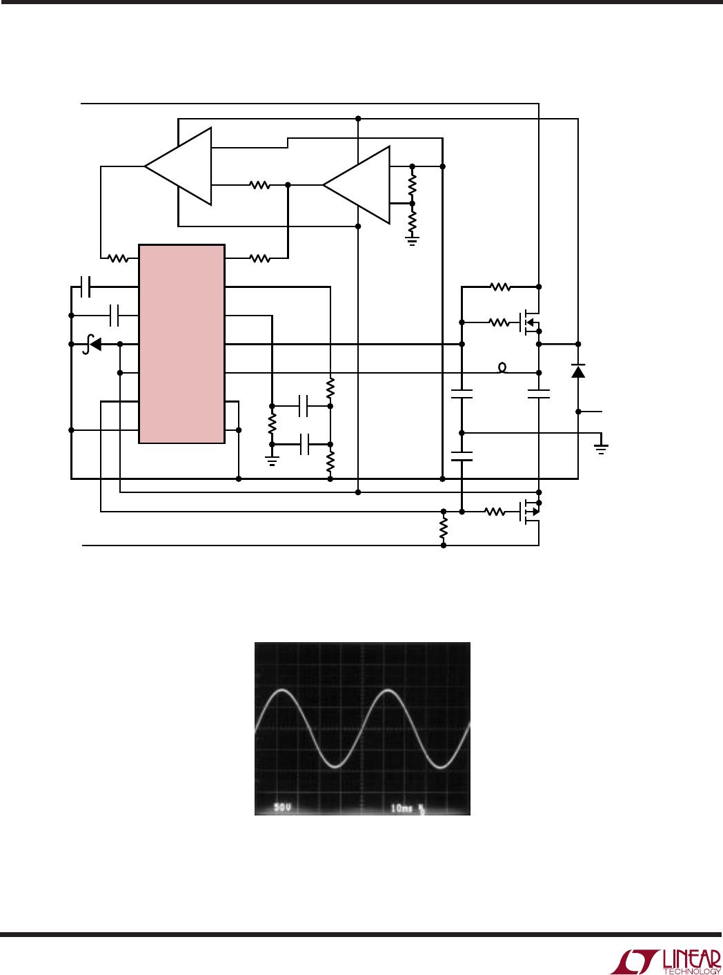
Active Filter Tuned Oscillator Block Diagram
The LT1684 can be implemented easily into a telephone
ringer circuit based on the active filter tuned oscillator
topology, eliminating the need for a user-supplied PWM
input signal. The LT1684’s active filter amplifier can be
used as a high-Q bandpass filter element by configuring
it as an active tracking supply bandpass. The LT1684’s
controlled output receiver/buffer is also convenient for
use as the hard limiter. Because the LT1684 receiver/
buffer requires a true differential input for proper opera-
tion, a dual comparator IC such as the LT1017 must be
bootstrapped along with the LT1684 to provide differen-
tial control signals. The LT1017 and LT1684 receiver/
buffer combine to create a high gain hard limiter whose
output is controlled to ±1.25V. The LT1684 active
bandpass filter is then connected as a positive feedback
element with the limiter component, which completes
the active filter tuned oscillator topology.
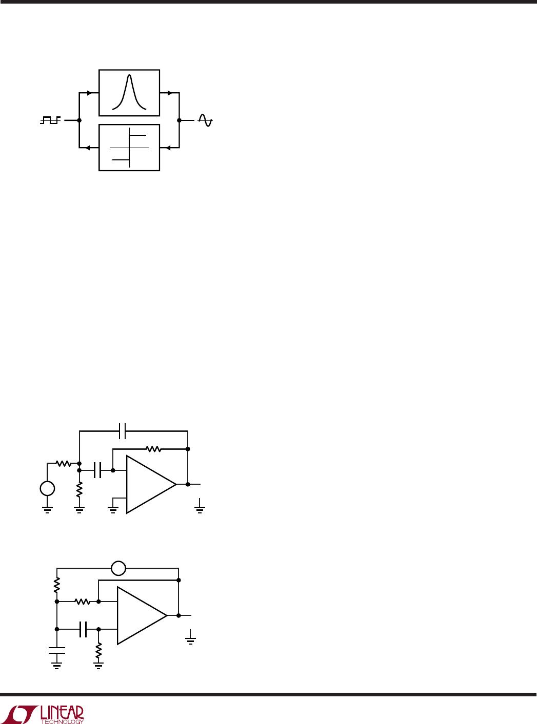
The active bandpass filter circuit is easily configured using
a basic MFB bandpass configuration, however, the active
tracking supply technique used by the LT1684 requires
“transformation” of this topology. This “transformation”
swaps the amplifier signal polarity, references all signals
to the output, and references all feedback elements to
ground as described previously in the Filter Design and
Component Selection section.
The design equations for the active tracking bandpass
filter are the same as the pretransformation MFB topology,
such that if C
F1
= C
F2
= C:
R
F1
= Q/(ω
O
• C •H
0
)
R
F2
= Q/(2Q
2
H
0
)(ω
O
• C)
R
F3
= 2Q/(ω
O
• C)
Example:
Conditions: Output peak voltage = 95V
Ring frequency = 20Hz
Bandpass Q = 9.4
A square wave with peak amplitude A has a fundamental
component with amplitude 4A/π, where A = 1.25V. There-
fore, the desired filter’s bandpass gain H
O
= 95/(4 •
1.25/π) ~ 60. Given capacitor values C = 0.22µF (a conve-
nient value) and desired filter characteristics of: Q = 9.4,
H
O
= 60, ω
O
= 2π(20Hz), then: R
F1
= 5.6k, R
F2
= 2.7k,
R
F3
= 680k. The amplitude, frequency and envelope re-
sponse time of the output signal can be adjusted by simply
changing the values of resistors R
F1
to R
F3
accordingly.
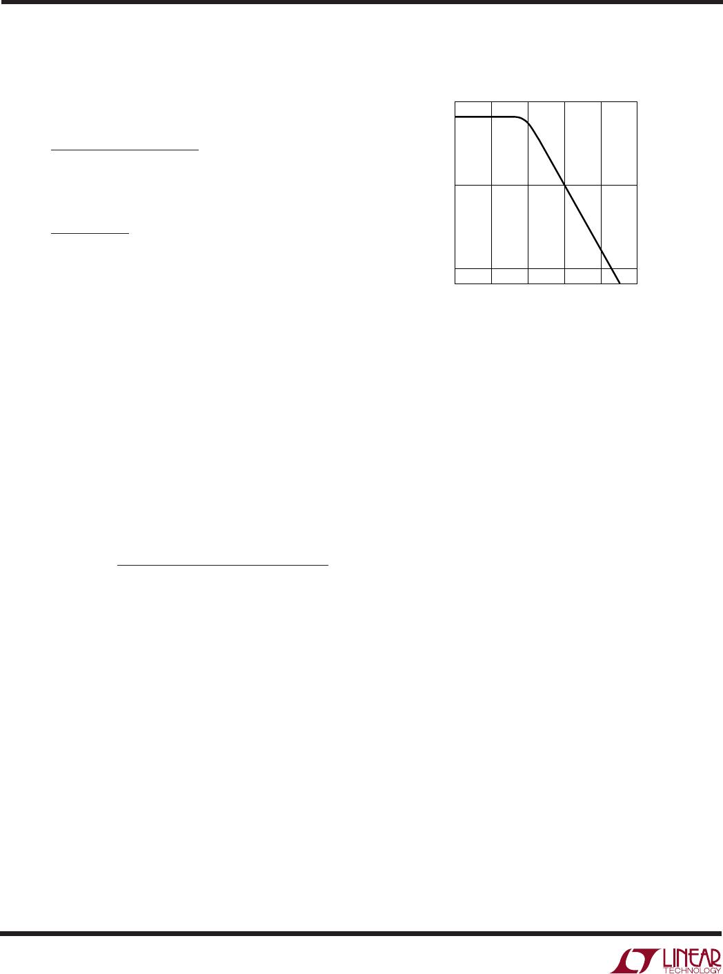
This produces a high voltage, high quality 20Hz sine wave
at the filter output with a peak amplitude of 95V. Differen-
tial amplitude and frequency characteristics are achieved
by simply changing a few resistor values. The output of the
LT1684 is internally current limited to a minimum of
±100mA peak, allowing this ring tone generation circuit to
be used with loads up to 7 REN with no degradation of the
output waveform.
+
R
F2
+
R
F1
V
IN
C
F2
R
F3
C
F1
V
OUT
1684 F5b
Bandpass MFB Filter
Active Tracking Bandpass MFB Filter
1684 F03
APPLICATIO S I FOR ATIO
WUUU
12
LT1684
IN B
COMP1
COMP2
LIM
V
GATE
AT
REF
IN A
BG
OUT
AMPIN
GATE
+
LT1684
V
+
LIM
+
OUT
1
2
3
4
5
6
110V
110V
7
14
13
12
11
10
9
8
R10
10k
C2
100pF
D1
1N5817
C1 20pF
R8
10k
R
F1
5.6k
R3
100k
R2
100
FB1
M1
IRF610
M2
IRF9610
C5
0.1µF
D2
1N4001
OUTPUT
1684 F05a
+
C4
6.8nF
R1 100
R
F2
2.7k
R4
100k
R
F3
680k
C
F1
0.22µF
C
F2
0.22µF
R9
10k
R6
1k
+
1/2 LT1017
V
+
8
7
4
5
6V
+
1/2 LT1017
V
+
8
4
3
2
1
V
R5
100k
C3
6.8nF
±100mA
PEAK
()
FB1: FERRONICS FMB1601 (716) 388-1020
Active Filter Tuned Oscillator Ring Tone Generator
Ringer Output
APPLICATIO S I FOR ATIO
WUUU

LT1684IS#TRPBF

Mfr. #:
Manufacturer:
Analog Devices / Linear Technology
Description:
Gate Drivers uP Ring Tone Gen
Lifecycle:
New from this manufacturer.
Delivery:
DHL FedEx Ups TNT EMS
Payment:
T/T Paypal Visa MoneyGram Western Union