VS-ST780C06L1

VS-ST780CL Series
www.vishay.com
Vishay Semiconductors
Revision: 15-Apr-14
4
Document Number: 94415
For technical questions within your region: DiodesAmericas@vishay.com
, DiodesAsia@vishay.com, DiodesEurope@vishay.com
THIS DOCUMENT IS SUBJECT TO CHANGE WITHOUT NOTICE. THE PRODUCTS DESCRIBED HEREIN AND THIS DOCUMENT
ARE SUBJECT TO SPECIFIC DISCLAIMERS, SET FORTH AT www.vishay.com/doc?91000
Fig. 1 - Current Ratings Characteristics
Fig. 2 - Current Ratings Characteristics
Fig. 3 - Current Ratings Characteristics
Fig. 4 - Current Ratings Characteristics
Fig. 5 - On-State Power Loss Characteristics
Fig. 6 - On-State Power Loss Characteristics
40
50
60
70
80
90
100
110
120
130
0 200 400 600 800 1000
30°
60°
90°
120°
180°
Average On-state Current (A)
Conduction Angle
Maximum Allowable Heatsink Temperature (°C)
ST7 8 0 C . . L Se r i e s
(Single Side Cooled)
R (DC) = 0.073 K/ W
thJ-hs
20
30
40
50
60
70
80
90
100
110
120
130
0 200 400 600 800 1000 1200 1400
DC
30°
60°
90°
120°
180°
Average On-state Current (A)
Conduction Period
Maximum Allowable Heatsink Temperature (°C)
ST7 8 0 C . . L Se r i e s
(Single Side Cooled)
R (DC) = 0.073 K/ W
thJ-hs
20
30
40
50
60
70
80
90
100
110
120
130
0 400 800 120016002000
30°
60°
90°
120°
180°
Average On-state Current (A)
Conduction Angle
Maximum Allowable Heatsink Temperature (°C)
ST780C..L Serie s
(Double Side Cooled)
R (DC) = 0.031 K/ W
thJ-hs
20
30
40
50
60
70
80
90
100
110
120
130
0 500 1000 1500 2000 2500 3000
DC
30°
60°
90°
120°
180°
Average On-state Current (A)
Conduction Period
Maximum Allowable Heatsink Temperature (°C)
ST7 8 0 C . . L Se r i e s
(Double Side Cooled)
R (DC) = 0.031 K/ W
thJ-hs
0
500
1000
1500
2000
2500
0 400 800 1200 1600 2000
180°
120°
90°
60°
30°
RM S Li m it
Conduction Angle
Maximum Average On-state Power Loss (W)
Average On-state Current (A)
ST780C..L Serie s
T = 125°C
J
0
500
1000
1500
2000
2500
3000
3500
0 500 1000 1500 2000 2500 3000
DC
180°
120°
90°
60°
30°
RM S Li m i t
Conduction Period
Maximum Average On-state Power Loss (W)
Average On-state Current (A)
ST780C..L Serie s
T = 125°C
J
VS-ST780CL Series
www.vishay.com
Vishay Semiconductors
Revision: 15-Apr-14
5
Document Number: 94415
For technical questions within your region: DiodesAmericas@vishay.com
, DiodesAsia@vishay.com, DiodesEurope@vishay.com
THIS DOCUMENT IS SUBJECT TO CHANGE WITHOUT NOTICE. THE PRODUCTS DESCRIBED HEREIN AND THIS DOCUMENT
ARE SUBJECT TO SPECIFIC DISCLAIMERS, SET FORTH AT www.vishay.com/doc?91000
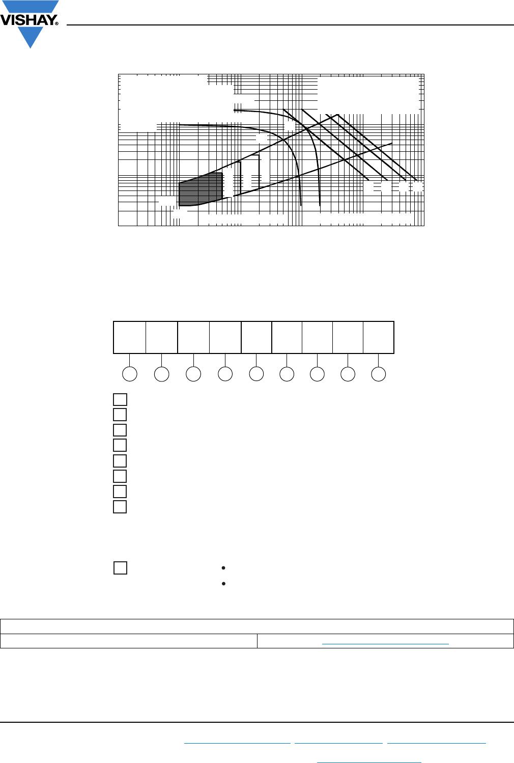
Fig. 7 - Maximum Non-Repetitive Surge Current
Single and Double Side Cooled
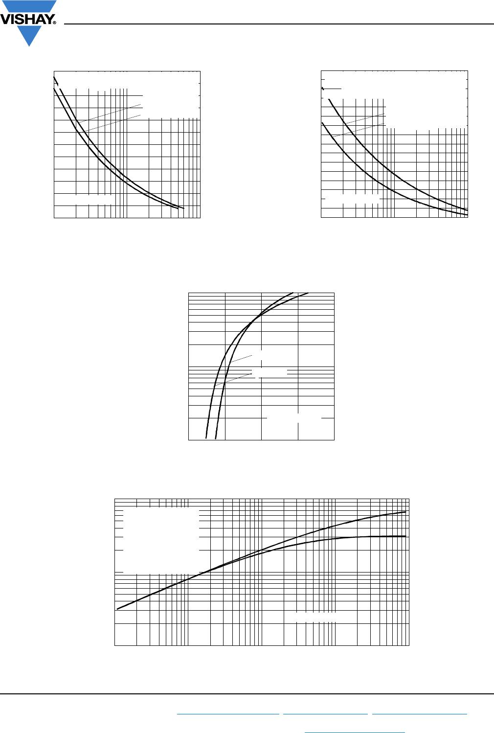
Fig. 8 - Maximum Non-Repetitive Surge Current
Single and Double Side Cooled
Fig. 9 - On-State Voltage Drop Characteristics
Fig. 10 - Thermal Impedance Z
thJ-hs
Characteristics
10000
12000
14000
16000
18000
20000
22000
110100
Number Of Equal Amplitude Ha lf Cyc le Current Pulses (N)
Peak Half Sine Wave On-st ate Current (A)
Initia l T = 125°C
@ 60 Hz 0.0083 s
@ 50 Hz 0.0100 s
J
ST7 8 0 C . . L Se r i e s
At Any Ra t ed Loa d Co nd it io n And Wit h
Rated V Applied Following Surge.
RRM
10000
12000
14000
16000
18000
20000
22000
24000
26000
0.01 0.1 1
Pulse Train Duration (s)
Versus Pulse Train Duration. Control
Peak Ha lf Sine Wave On-state Current (A)
Initia l T = 125°C
No Voltage Reapplied
Ra t e d V Re a p p l i e d
RRM
J
ST7 8 0 C . . L Se r i e s
Maximum Non Repetitive Surge Current
Of Conduction May Not Be Maintained.
100
1000
10000
0.5 1 1.5 2 2.5
T = 2 5 ° C
J
Instantaneous On-state Current (A)
Instantaneous On-state Voltage (V)
T = 1 2 5 ° C
J
ST7 8 0 C . . L Se r i e s
0.001
0.01
0.1
0.001 0.01 0.1 1 10
Sq u a r e W a v e Pu l se D u r a t i o n ( s)
thJ-hs
Steady State Value
R = 0.073 K/ W
(Single Side Cooled)
R = 0.031 K/ W
(Double Side Cooled)
(DC Operation)
thJ-hs
thJ-hs
ST7 8 0 C . . L Se r i e s
Transient Thermal Impedance Z (K/W)
VS-ST780CL Series
www.vishay.com
Vishay Semiconductors
Revision: 15-Apr-14
6
Document Number: 94415
For technical questions within your region: DiodesAmericas@vishay.com
, DiodesAsia@vishay.com, DiodesEurope@vishay.com
THIS DOCUMENT IS SUBJECT TO CHANGE WITHOUT NOTICE. THE PRODUCTS DESCRIBED HEREIN AND THIS DOCUMENT
ARE SUBJECT TO SPECIFIC DISCLAIMERS, SET FORTH AT www.vishay.com/doc?91000
Fig. 11 - Gate Characteristics
ORDERING INFORMATION TABLE
Device code
51 32 4 6 7 8 9
VS- ST 78 0 C 06 L 1 -
- Thyristor
2
- Essential part number
3
- 0 = Converter grade
4
- C = Ceramic PUK
5
- Voltage code x 100 = V
RRM
(see Voltage Ratings table)
6
- L = PUK case TO-200AC (B-PUK)
7
- 0 = Eyelet terminals (gate and auxiliary cathode unsoldered leads)
1 = Fast-on terminals (gate and auxiliary cathode unsoldered leads)
2 = Eyelet terminals (gate and auxiliary cathode soldered leads)
9
8
- Critical dV/dt:
None = 500 V/µs (standard selection)
L = 1000 V/µs (special selection)
3 = Fast-on terminals (gate and auxiliary cathode soldered leads)
1 - Vishay Semiconductors product
LINKS TO RELATED DOCUMENTS
Dimensions http://www.vishay.com/doc?95076

VS-ST780C06L1

Mfr. #:
Manufacturer:
Vishay Semiconductors
Description:
SCR Modules 1350 Amp 600 Volt 2700 Amp IT(RMS)
Lifecycle:
New from this manufacturer.
Delivery:
DHL FedEx Ups TNT EMS
Payment:
T/T Paypal Visa MoneyGram Western Union