SST25PF080B
DS20005137B-page 16 2014 Microchip Technology Inc.
4.8.5 WRITE-STATUS-REGISTER (WRSR)
The Write-Status-Register instruction writes new val-
ues to the BP2, BP1, BP0, and BPL bits of the status
register. CE# must be driven low before the command
sequence of the WRSR instruction is entered and
driven high before the WRSR instruction is executed.
See Figure 4-17 for EWSR or WREN and WRSR
instruction sequences.
Executing the Write-Status-Register instruction will be
ignored when WP# is low and BPL bit is set to “1”.
When the WP# is low, the BPL bit can only be set from
“0” to “1” to lock-down the status register, but cannot be
reset from “1” to “0”. When WP# is high, the lock-down
function of the BPL bit is disabled and the BPL, BP0,
BP1, and BP2 bits in the status register can all be
changed. As long as BPL bit is set to 0 or WP# pin is
driven high (V
IH
) prior to the low-to-high transition of the
CE# pin at the end of the WRSR instruction, the bits in
the status register can all be altered by the WRSR
instruction. In this case, a single WRSR instruction can
set the BPL bit to “1” to lock down the status register as
well as altering the BP0, BP1, and BP2 bits at the same
time. See Table 4-1 for a summary description of WP#
and BPL functions.
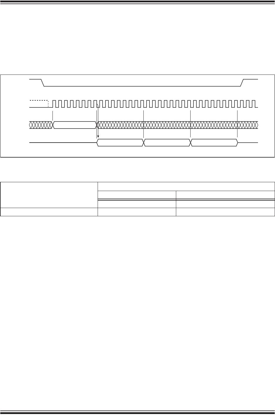
FIGURE 4-17: ENABLE-WRITE-STATUS-REGISTER (EWSR) OR WRITE-ENABLE (WREN) AND
WRITE-STATUS-REGISTER (WRSR) SEQUENCE
25137 EWSR.0
MODE 3
HIGH IMPEDANCE
MODE 0
STATUS
REGISTER IN
76543210
MSBMSBMSB
01
MODE 3
SCK
SI
SO
CE#
MODE 0
50 or 06
0 1 2 3 4 5 6 7 0 1 2 3 4 5 6 7 8 9 10 11 12 13 14 15
2014 Microchip Technology Inc. DS20005137B-page 17
SST25PF080B
4.8.6 JEDEC READ-ID
The JEDEC Read-ID instruction identifies the device as
SST25PF080B and the manufacturer as Microchip.
The device information can be read from executing the
8-bit command, 9FH. Following the JEDEC Read-ID
instruction, the 8-bit manufacturer’s ID, BFH, is output
from the device. After that, a 16-bit device ID is shifted
out on the SO pin. Byte 1, BFH, identifies the manufac-
turer as Microchip. Byte 2, 25H, identifies the memory
type as SPI Serial Flash. Byte 3, 8EH, identifies the
device as SST25PF080B. The instruction sequence is
shown in Figure 4-18. The JEDEC Read ID instruction
is terminated by a low to high transition on CE# at any
time during data output.
FIGURE 4-18: JEDEC READ-ID SEQUENCE
25 8E
25137 JEDECID.1
CE#
SO
SI
SCK
012345678
HIGH IMPEDANCE
15 1614 28 29 30 31
BF
MODE 3
MODE 0
MSBMSB
9 10111213 1718 32 34
9F
19 20 21 22 23 3324 25 26 27
TABLE 4-6: JEDEC READ-ID DATA
Manufacturer’s ID
Device ID
Memory Type Memory Capacity
Byte1 Byte 2 Byte 3
BFH 25H 8EH
SST25PF080B
DS20005137B-page 18 2014 Microchip Technology Inc.
4.8.7 READ-ID (RDID)
The Read-ID instruction (RDID) identifies the devices
as SST25PF080B and manufacturer as Microchip. This
command is backward compatible and should be used
as default device identification when multiple versions
of SPI Serial Flash devices are used in a design. The
device information can be read from executing an 8-bit
command, 90H or ABH, followed by address bits [A
23
-
A
0
]. Following the Read-ID instruction, the manufac-
turer’s ID is located in address 00000H and the device
ID is located in address 00001H. Once the device is in
Read-ID mode, the manufacturer’s and device ID out-
put data toggles between address 00000H and 00001H
until terminated by a low to high transition on CE#.
Refer to Tables 4-6 and 4-7 for device identification
data.
FIGURE 4-19: READ-ID SEQUENCE
25137 RdID.0
CE#
SO
SI
SCK
00
012345678
00 ADD
1
90 or AB
HIGH IMPEDANCE
15 16
23
24
31
32
39
40
47 48 55 56 63
BF
Device ID
BF
Device ID
Note: The manufacturer s and device ID output stream is continuous until terminated by a low to high transition on CE#.
Device ID = 8EH for SST25PF080B
1. 00H will output the manfacturer s ID first and 01H will output device ID first before toggling between the two.
HIGH
IMPEDANCE
MODE 3
MODE 0
MSB MSB
MSB
TABLE 4-7: PRODUCT IDENTIFICATION
Address Data
Manufacturer’s ID 00000H BFH
Device ID
SST25PF080B 00001H 8EH

SST25PF080B-80-4C-QAE

Mfr. #:
Manufacturer:
Microchip Technology
Description:
NOR Flash 2.3V to 3.6V 8Mbit SPI Serial Flash
Lifecycle:
New from this manufacturer.
Delivery:
DHL FedEx Ups TNT EMS
Payment:
T/T Paypal Visa MoneyGram Western Union