Symbol
Typ
Parameter
Conditions Min
Max
Unit
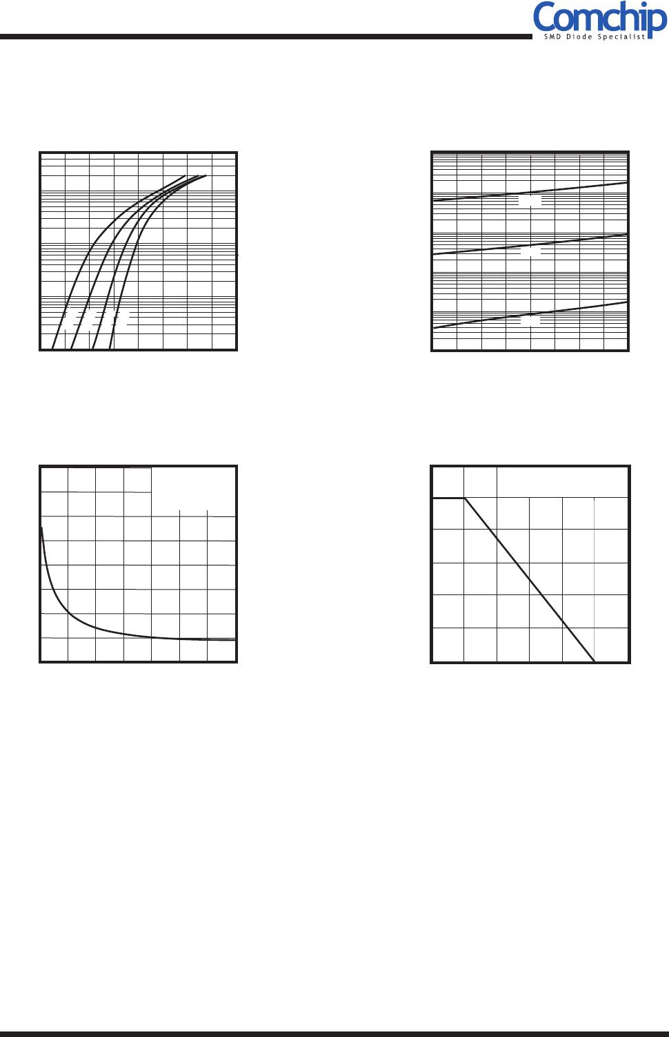
Forward voltage
CDBQR42/43-HF
CDBQR42-HF
CDBQR43-HF
CDBQR42-HF
CDBQR43-HF
IF = 10mA
IF = 200mA
IF = 50mA
IF = 2mA
IF = 15mA
VF V
0.4
1
0.65
0.33
0.45
Reverse current
Capacitance between terminals
Reverse recovery time
VR = 25V
f = 1 MHz, and 1 VDC reverse voltage
IF=IR=10mA,Irr=0.1xIR,RL=100 ohm
IR
CT
Trr
uA
pF
nS
5
10
0.5
CDBQR42/43-HF
SMD Schottky Barrier Diode
QW-G1101
O
Maximum Rating (at TA=25 C unless otherwise noted)
O
Electrical Characteristics (at TA=25 C unless otherwise noted)
Page 1
Typ
IO
IFSM
VR(RMS)
VR
VRM
IFRM
Repetitive peak forward current
Average forward rectified current
Reverse voltage
Peak reverse voltage
Forward current,surge peak
Symbol
Parameter
Conditions
Min
Max
Unit
RMS reverse voltage
8.3 ms single half sine-wave superimposed
on rate load(JEDEC method)
A
A
mA
V
V
V
4
0.5
200
21
30
30
TSTG
Tj
Storage temperature
Junction temperature
O
C
O
C
+125
+125
-55
PD
Power dissipation
Thermal resistance junction
to ambient air
mW
O
C/W
125
667R JA
REV:B
Features
-Low forward voltage.
-Designed for mounting on small surface.
-Extremely thin/leadless package.
-Majority carrier conduction.
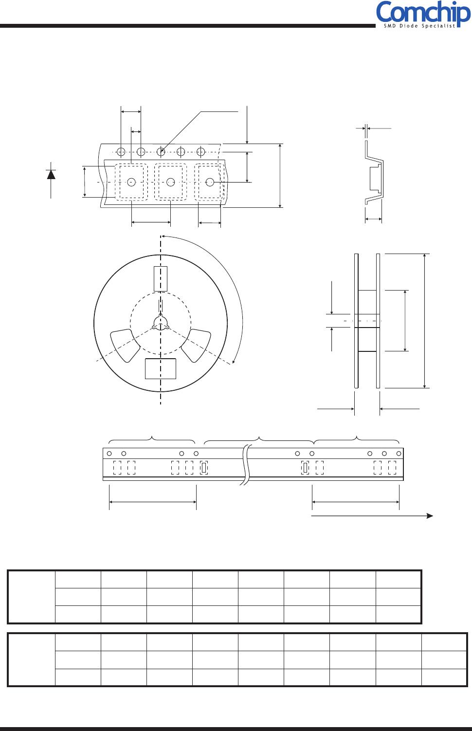
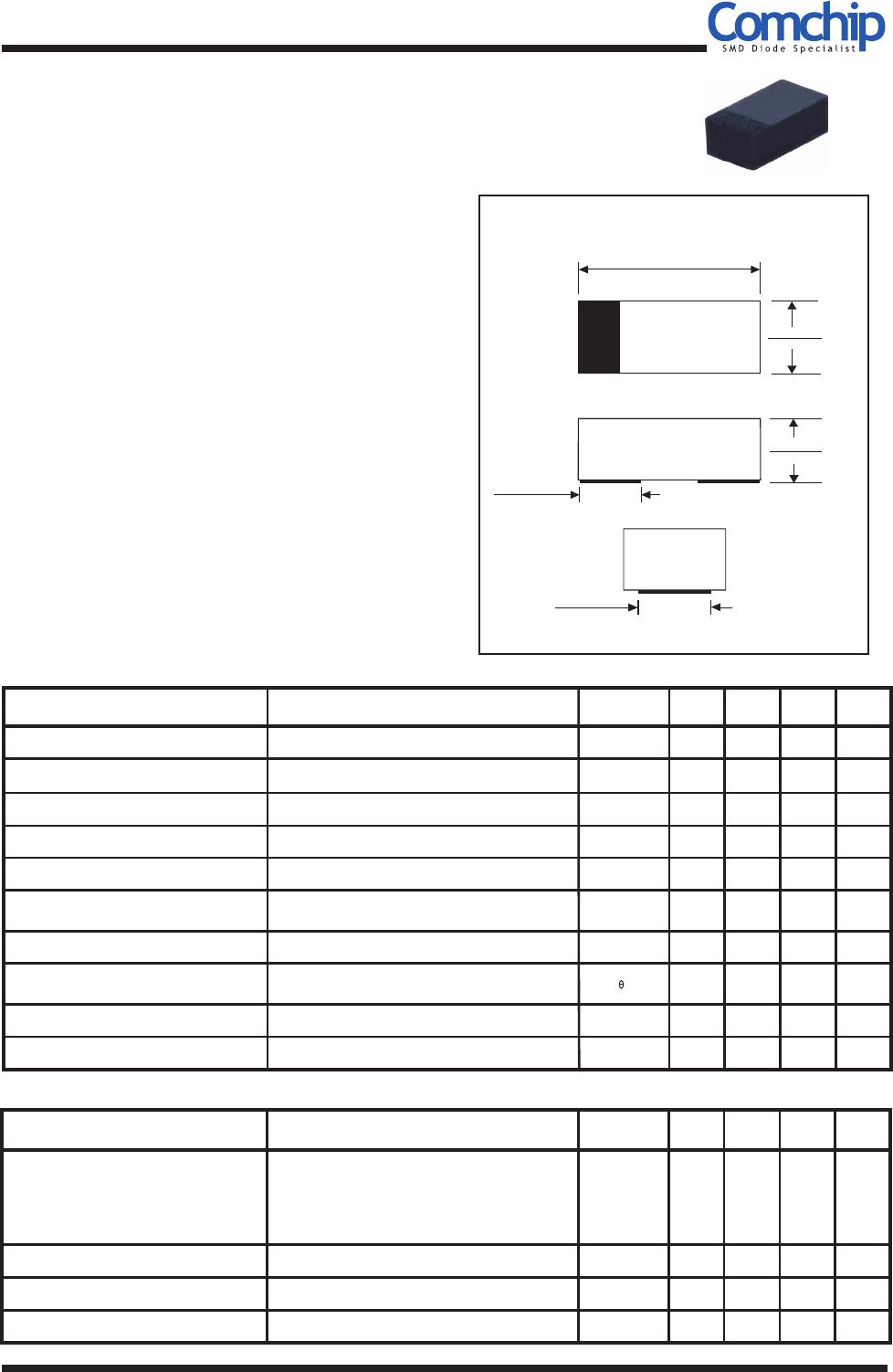
Mechanical data
-Case: 0402 standard package,
molded plastic.
-Terminals: Gold plated, solderable per
MIL-STD-750,method 2026.
-Marking code:
CDBQR42-HF : BD
CDBQR43-HF : BE
-Mounting position: Any
-Weight: 0.001 gram(approx.).
/SOD-923F
Comchip Technology CO., LTD.
0.041(1.05)
0.037(0.95)
0.026(0.65)
0.022(0.55)
Dimensions in inches and (millimeter)
0.020(0.50) Typ.
0.022(0.55)
0.018(0.45)
0.012(0.30) Typ.
0402/SOD-923F
Io = 200 mA
VR = 30 Volts
RoHS Device
Halogen Free