Si8220/21
10 Rev. 1.2
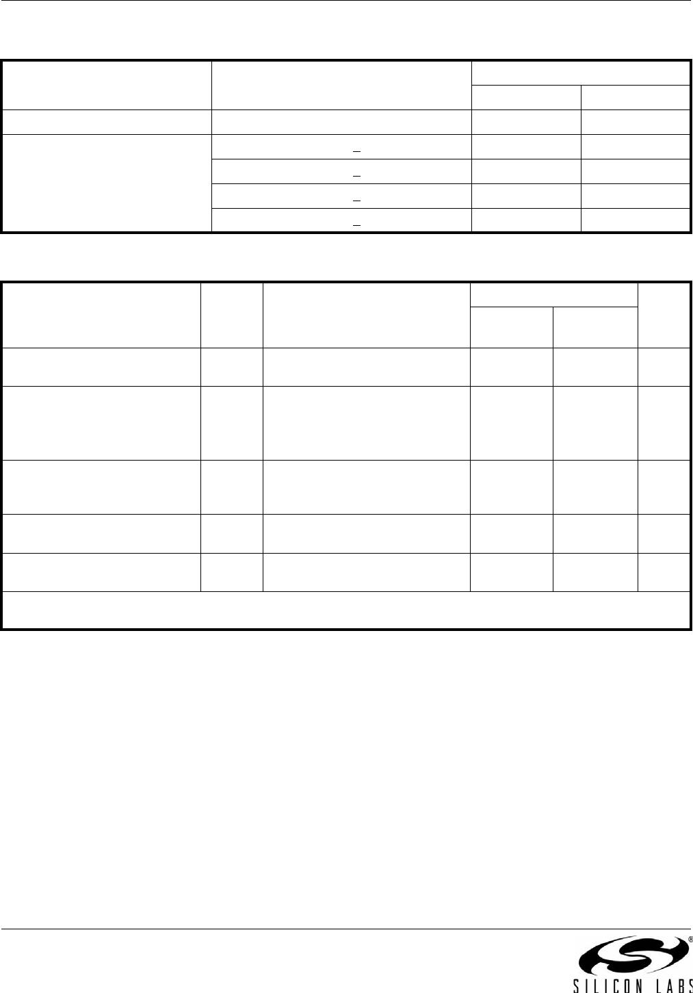
Table 4. IEC 60664-1 (VDE 0844 Part 2) Ratings
Parameter Test Conditions
Specification
NB SOIC8 WB SOIC 16
Basic Isolation Group Material Group I I
Installation Classification
Rated Mains Voltages <
150 V
RMS
I-IV I-IV
Rated Mains Voltages <
300 V
RMS
I-III I-IV
Rated Mains Voltages <
400 V
RMS
I-II I-III
Rated Mains Voltages <
600 V
RMS
I-II I-III
Table 5. IEC 60747-5-2 Insulation Characteristics for Si822xxC*
Parameter Symbol Test Condition
Characteristic
Unit
WB
SOIC-16
NB SOIC-8
Maximum Working Insulation
Voltage
V
IORM
891 560 V peak
Input to Output Test Voltage
V
PR
Method b1
(V
IORM
x1.875=V
PR
, 100%
Production Test, t
m
= 1 sec,
Partial Discharge < 5 pC)
1671 1050
V peak
Highest Allowable Overvoltage
(Transient Overvoltage,
t
TR
=60sec)
V
TR
6000 4000 V peak
Pollution Degree
(DIN VDE 0110, Table 1)
22
Insulation Resistance at T
S
,
V
IO
=500V
R
S
>10
9
>10
9
*Note: This isolator is suitable for basic electrical isolation only within the safety limit data. Maintenance of the safety data is
ensured by protective circuits. The Si822x provides a climate classification of 40/125/21.
Si8220/21
Rev. 1.2 11
Figure 4. (WB SOIC-16) Thermal Derating Curve, Dependence of Safety Limiting Values
with Case Temperature per DIN EN 60747-5-2
Table 6. IEC Safety Limiting Values
1
Parameter Symbol Test Condition
Max
Unit
WB SOIC-16 NB SOIC-8
Case Temperature T
S
150 150 °C
Safety Input, Output, or
Supply Current
I
S
JA
= 140 °C/W (NB SOIC-8),
100 °C (WB SOIC-16),
V
I
= 5.5 V, T
J
=15C, T
A
=2C
50 40 mA
Device Power Dissipation
2
P
D
1.2 1.2 W
Notes:
1. Maximum value allowed in the event of a failure; also see the thermal derating curve in Figures 5 and 6.
2. The Si822x is tested with V
O
=24V, T
J
=15C, C
L
= 200 pF, input a 2 MHz 50% duty cycle square wave.
Table 7. Thermal Characteristics
Parameter Symbol
Typ
Unit
WB SOIC-16 NB SOIC-8
IC Junction-to-Air Thermal
Resistance
JA
100 140 ºC/W
0 20015010050
60
40
20
0
Case Temperature (ºC)
Safety-Limiting Current (mA)
VDD = 24 V
10
30
50
Si8220/21
12 Rev. 1.2
Figure 5. (NB SOIC-8) Thermal Derating Curve, Dependence of Safety Limiting Values
with Case Temperature per DIN EN 60747-5-2
Table 8. Absolute Maximum Ratings
1
Parameter Conditions Min Typ Max Units
Storage Temperature
2
T
STG
–65 +150 C
Operating Temperature –40 +125 C
Output Supply Voltage V
DD
–0.6 30 V
Output Voltage V
O
–0.5 V
DD
+ 0.5 V
Output Current Drive I
O
——10mA
Input Current IF
(AVG)
–100 30 mA
Lead Solder Temperature (10 s) 260 C
Maximum Isolation Voltage (1 s) NB SOIC-8 4250 V
RMS
Maximum Isolation Voltage (1 s) WB SOIC-16 6500 V
RMS
Notes:
1. Permanent device damage may occur if the absolute maximum ratings are exceeded. Functional operation should be
restricted to the conditions specified in the operational sections of this data sheet.
2. VDE certifies storage temperature from –40 to 150 °C.
0 20015010050
60
40
20
0
Case Temperature (ºC)
Safety-Limiting Current (mA)
VDD = 24 V
10
30
50

SI8220BD-D-ISR

Mfr. #:
Manufacturer:
Silicon Labs
Description:
Gate Drivers 5 kV opto input isolated gate driver
Lifecycle:
New from this manufacturer.
Delivery:
DHL FedEx Ups TNT EMS
Payment:
T/T Paypal Visa MoneyGram Western Union