MAX1620/MAX1621
Digitally Adjustable LCD Bias Supplies
______________________________________________________________________________________ 13
Reserved for future use.
DAC Register Data
Reserved for future use.
If the voltage applied to POK is
greater than 0.992V and the
MAX1621 is not shut down, this bit
returns 1; otherwise, it returns 0.
DESCRIPTION
5
D4 (MSB)
D3
D2
D1
D0
4
3
2
1
0
6
POK7
NAMEBIT
With SUS = high,
1 = LCD on, and
0 = LCD off.
DAC Input Data
With SUS = high,
1 = operating, and
0 = shutdown.
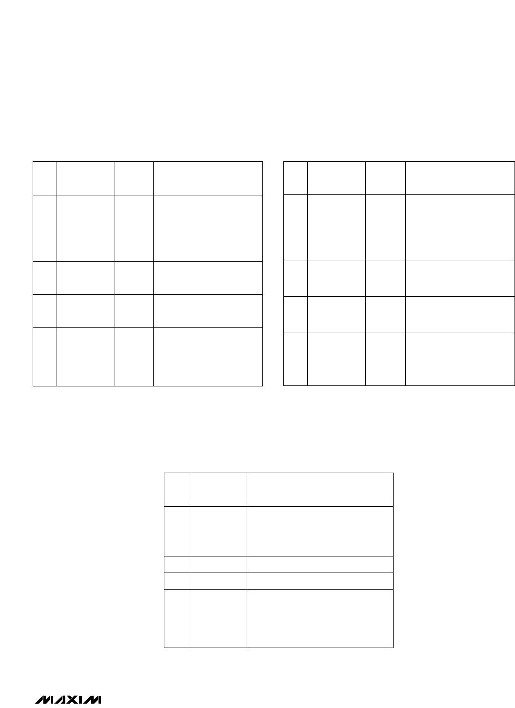
Register Select. A one in
this bit writes the next two
bits into the OPR register
and the remaining five bits
into the DAC register
(Figure 7).
DESCRIPTION
1OPR-LCDON5
1
0
0
0
0
D4 (MSB)
D3
D2
D1
D0
4
3
2
1
0
1
OPR-SHDN
6
REGSEL7
NAME
POR
STATE*
BIT
Table 2. MAX1621 Configuration Byte
with REGSEL = 1 (write to OPR register)
*
Initial register state after power-up.
Table 3. MAX1621 Status Bits
With SUS = low,
1 = LCD on, and
0 = LCD off.
DAC Input Data
With SUS = low,
1 = operating, and
0 = shutdown.
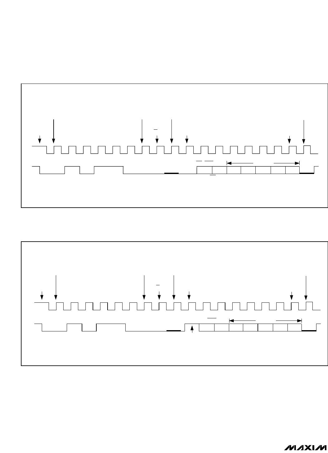
Register Select. A zero in
this bit writes the next two
bits into the SUS register
and the remaining five bits
into the DAC register
(Figure 7).
DESCRIPTION
0
SUS-LCDON
5
1
0
0
0
0
D4 (MSB)
D3
D2
D1
D0
4
3
2
1
0
0
SUS-SHDN
6
REGSEL7
POR
STATE*
BIT NAME
*
Initial register state after power-up.
Table 1. MAX1621 Configuration Byte
with REGSEL = 0 (write to SUS register)
START
CONDITION
MOST
SIGNIFICANT
ADDRESS BIT
LEAST
SIGNIFICANT
ADDRESS BIT
SLAVE
PULLS
SDA LOW
SLAVE
PULLS
SDA LOW
REGSEL
D4
OPR-LCDON
OPR-SHDN
D3 D2 D1 D0
SLAVE
ACKNOWLEDGE
SLAVE
ACKNOWLEDGE
MOST
SIGNIFICANT
DATA BIT
LEAST
SIGNIFICANT
DATA BIT
SCL
SDA
R/W BIT
DAC DATA
Figure 8. MAX1621 Serial-Interface Single-Byte Write Example (REGSEL = 1)
MAX1620/MAX1621
Digitally Adjustable LCD Bias Supplies
14 ______________________________________________________________________________________
START
CONDITION
MOST
SIGNIFICANT
ADDRESS BIT
LEAST
SIGNIFICANT
ADDRESS BIT
SLAVE PULLS
SDA LOW
SLAVE PULLS
SDA LOW
REGSEL
D4
SUS-SHDN DAC DATA
D3 D2 D1 D0
SLAVE
ACKNOWLEDGE
SLAVE
ACKNOWLEDGE
MOST
SIGNIFICANT
DATA BIT
LEAST
SIGNIFICANT
DATA BIT
SCL
SDA
R/W BIT
SUS-LCDON
Figure 7. MAX1621 Serial-Interface Single-Byte Write Example (REGSEL = 0)
MAX1620/MAX1621
Digitally Adjustable LCD Bias Supplies
______________________________________________________________________________________ 15
START
CONDITION
MOST
SIGNIFICANT
ADDRESS BIT
LEAST
SIGNIFICANT
ADDRESS BIT
SLAVE PULLS
SDA LOW
MAX1621 DRIVES SDA
D4POK D3 D2 D1 D0
SLAVE
ACKNOWLEDGE
MOST
SIGNIFICANT
DATA BIT
SCL
SDA
R/W BIT
Figure 9. MAX1621 Serial-Interface Read Example
Design Procedure
__________and Component Selection
The MAX1620/MAX1621 output voltage can be adjusted
manually or via a digital interface. In addition, positive
bias voltage can be switched with LCDON using an
external PFET or PNP transistor.
Output Adjustment
Setting the Minimum Output Voltage
The minimum output voltage is set with a resistor-divider
(R4-R5, Figure 4) from V
OUT
to AGND. The FB threshold
voltage is 1.5V. Choose R4 to be 300k so that the cur-
rent in the divider is about 5µA. Determine R5 as follows:
R5 = R4 x (V
OUT,MIN
- V
FB
) / V
FB
For example, if V
OUT,MIN
= 12.5V:
R5 = 300kx (12.5 - 1.5) / (1.5) = 2.2M
Mount R4 and R5 close to the FB pin to minimize para-
sitic capacitance.
For a negative output voltage, the FB threshold voltage
is 0V, and R4 is placed between FB and REF (Figures 5
and 6). Again, choose R4 to be 300k so that the cur-
rent in the divider is about 5µA. Then determine R5 as
follows:
R5 = R4 x V
OUT,MIN
/ V
REF
For example, if V
OUT,MIN
= -12.5V:
R5 = 300kx (12.5) / (1.5)= 2.5M

MAX1620EEE+

Mfr. #:
Manufacturer:
Maxim Integrated
Description:
Power Management Specialized - PMIC Digitally Adjustable LCD Bias Supply
Lifecycle:
New from this manufacturer.
Delivery:
DHL FedEx Ups TNT EMS
Payment:
T/T Paypal Visa MoneyGram Western Union

Products related to this Datasheet