ADuM240D/ADuM240E/ADuM241D/ADuM241E/ADuM242D/ADuM242E Data Sheet
Rev. A | Page 10 of 26
Parameter Symbol Min Typ Max Unit Test Conditions/Comments
Undervoltage Lockout UVLO
Positive V
DDx
Threshold V
DDxUV+
1.6 V
Negative V
DDx
Threshold V
DDxUV−
1.5 V
V
DDx
Hysteresis V
DDxUVH
0.1 V
AC SPECIFICATIONS
Output Rise/Fall Time t
R
/t
F
2.5 ns 10% to 90%
Common-Mode Transient Immunity
7
|CM
H
| 75 100 kV/µs
V
Ix
= V
DDx
, V
CM
= 1000 V,
transient magnitude = 800 V
|CM
L
| 75 100 kV/µs
V
Ix
= 0 V, V
CM
= 1000 V,
transient magnitude = 800 V
1
150 Mbps is the highest data rate that can be guaranteed, although higher data rates are possible.
2
I
Ox
is the Channel x output current, where x = A, B, C, or D.
3
V
IxH
is the input side logic high.
4
V
IxL
is the input side logic low.
5
V
I
is the voltage input.
6
E0 is the ADuM240E0/ADuM241E0/ADuM242E0 models, D0 is the ADuM240D0/ADuM241D0/ADuM242D0 models, E1 is the ADuM240E1/ADuM241E1/ADuM242E1
models, and D1 is the ADuM240D1/ADuM241D1/ADuM242D1 models. See the Ordering Guide section.
7
|CM
H
| is the maximum common-mode voltage slew rate that can be sustained while maintaining the voltage output (V
O
) > 0.8 V
DDx
. |CM
L
| is the maximum common-
mode voltage slew rate that can be sustained while maintaining V
O
> 0.8 V. The common-mode voltage slew rates apply to both rising and falling common-mode
voltage edges.
Table 8. Total Supply Current vs. Data Throughput
1 Mbps 25 Mbps 100 Mbps
Parameter Symbol Min Typ Max Min Typ Max Min Typ Max Unit
SUPPLY CURRENT
ADuM240D/ADuM240E
Supply Current Side 1 I
DD1
6.4 9.8 7.2 11 10.2 15.2 mA
Supply Current Side 2 I
DD2
1.9 3.5 3.1 5.0 6.8 10 mA
ADuM241D/ADuM240E
Supply Current Side 1 I
DD1
5.5 9.1 6.3 10.0 9.6 14.0 mA
Supply Current Side 2 I
DD2
3.72 6.45 4.8 7.5 8.4 11.2 mA
ADuM242D/ADuM242E
Supply Current Side 1 I
DD1
4.3 7.7 5.3 8.7 8.6 12.6 mA
Supply Current Side 2 I
DD2
4.9 8.3 6.0 9.4 9.3 13.3 mA
Data Sheet ADuM240D/ADuM240E/ADuM241D/ADuM241E/ADuM242D/ADuM242E
Rev. A | Page 11 of 26
INSULATION AND SAFETY RELATED SPECIFICATIONS
For additional information, see www.analog.com/icouplersafety.
Table 9. RW-16 Wide Body [SOIC_W] Package
Parameter Symbol Value Unit Test Conditions/Comments
Rated Dielectric Insulation Voltage 5000 V rms 1-minute duration
Minimum External Air Gap (Clearance) L (I01) 7.8 mm min
Measured from input terminals to output terminals,
shortest distance through air
Minimum External Tracking (Creepage) L (I02) 7.8 mm min
Measured from input terminals to output terminals,
shortest distance path along body
Minimum Clearance in the Plane of the Printed
Circuit Board (PCB Clearance)
L (PCB) 8.1 mm min
Measured from input terminals to output terminals,
shortest distance through air, line of sight, in the PCB
mounting plane
Minimum Internal Gap (Internal Clearance) 25.5 m min Insulation distance through insulation
Tracking Resistance (Comparative Tracking Index) CTI >400 V DIN IEC 112/VDE 0303 Part 1
Material Group II Material Group (DIN VDE 0110, 1/89, Table 1)
Table 10. RI-16 -2 Wide Body Increased Creepage [SOIC_IC] Package
Parameter Symbol Value Unit Test Conditions/Comments
Rated Dielectric Insulation Voltage 5000 V rms 1-minute duration
Minimum External Air Gap (Clearance) L (I01) 8.3 mm min
Measured from input terminals to output terminals,
shortest distance through air
Minimum External Tracking (Creepage) L (I02) 8.3 mm min
Measured from input terminals to output terminals,
shortest distance path along body
Minimum Clearance in the Plane of the Printed
Circuit Board (PCB Clearance)
L (PCB) 8.3 mm min
Measured from input terminals to output terminals,
shortest distance through air, line of sight, in the PCB
mounting plane
Minimum Internal Gap (Internal Clearance) 25.5 m min Insulation distance through insulation
Tracking Resistance (Comparative Tracking Index) CTI >400 V DIN IEC 112/VDE 0303 Part 1
Material Group II Material Group (DIN VDE 0110, 1/89, Table 1)
PACKAGE CHARACTERISTICS
Table 11.
Parameter Symbol Min Typ Max Unit Test Conditions/Comments
Resistance (Input to Output)
1
R
I-O
10
13
Capacitance (Input to Output)
1
C
I-O
2.2 pF f = 1 MHz
Input Capacitance
2
C
I
4.0 pF
IC Junction to Ambient Thermal Resistance θ
JA
45 °C/W Thermocouple located at center of package underside
1
The device is considered a 2-terminal device: Pin 1 through Pin 8 are shorted together, and Pin 9 through Pin 16 are shorted together.
2
Input capacitance is from any input data pin to ground.
ADuM240D/ADuM240E/ADuM241D/ADuM241E/ADuM242D/ADuM242E Data Sheet
Rev. A | Page 12 of 26
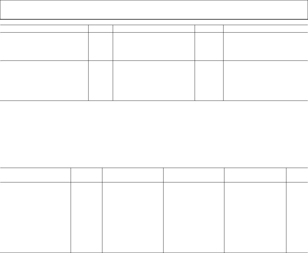
REGULATORY INFORMATION
See Table 17, Table 18, and the Insulation Lifetime section for details regarding recommended maximum working voltages for specific
cross-isolation waveforms and insulation levels.
Table 12. RW-16 Wide Body [SOIC_W] Package
UL (Pending) CSA (Pending) VDE (Pending) CQC (Pending)
Recognized Under UL 1577
Component Recognition
Program
1
Approved under CSA Component Acceptance
Notice 5A
Certified according to DIN V VDE V
0884-10 (VDE V 0884-10):2006-12
2
Certified by
CQC11-471543-2012,
GB4943.1-2011:
Single Protection, 5000 V rms
Isolation Voltage
CSA 60950-1-07+A1+A2 and IEC 60950-1,
second edition, +A1+A2:
Reinforced insulation, V
IORM
=
849 peak, V
IOSM
= 8000 V peak
Basic insulation at
780 V rms (1103 V peak)
Double Protection, 5000 V rms
Isolation Voltage
Basic insulation at 780 V rms (1103 V peak) Basic insulation, V
IORM
= 849 V peak,
V
IOSM
= 12 kV peak
Reinforced insulation at
389 V rms (552 V peak),
tropical climate, altitude
≤5000 meters
Reinforced insulation at 390 V rms
(552 V peak)
IEC 60601-1 Edition 3.1:
Basic insulation (1 means of patient protection
(1 MOPP)), 490 V rms (686 V peak)
Reinforced insulation (2 MOPP), 238 V rms
(325 V peak)
CSA 61010-1-12 and IEC 61010-1 third edition:
Basic insulation at 300 V rms mains, 780 V
secondary (1103 V peak)
Reinforced insulation at 300 V rms mains,
390 V secondary (552 V peak)
File E214100 File 205078 File 2471900-4880-0001 File (pending)
1
In accordance with UL 1577, each product is proof tested by applying an insulation test voltage ≥ 6000 V rms for 1 sec.
2
In accordance with DIN V VDE V 0884-10, each product is proof tested by applying an insulation test voltage ≥ 1592 V peak for 1 sec (partial discharge detection limit =
5 pC). The * marking branded on the component designates DIN V VDE V 0884-10 approval.
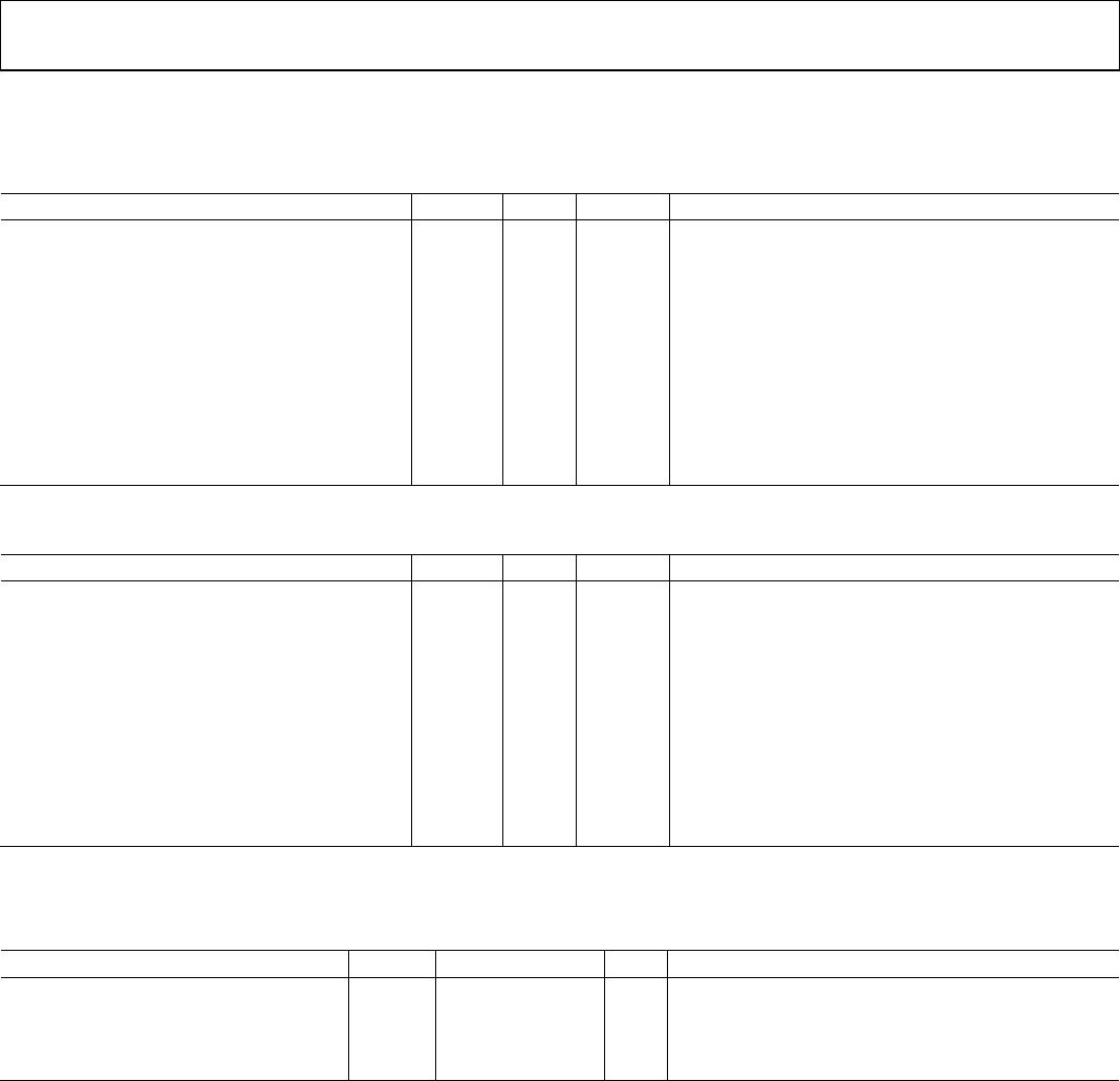
Table 13. RI-16 -2 Wide Body Increased Creepage [SOIC_IC] Package
UL (Pending) CSA (Pending) VDE (Pending) CQC (Pending)
Recognized Under 1577
Component Recognition
Program
1
Approved under CSA Component Acceptance
Notice 5A
Certified according to DIN V VDE V
0884-10 (VDE V 0884-10):2006-12
2
Certified by
CQC11-471543-2012,
GB4943.1-2011
Single Protection, 5000 V rms
Isolation Voltage
CSA 60950-1-07+A1+A2 and IEC 60950-1,
second edition, +A1+A2:
Reinforced insulation, V
IORM
=
849 peak, V
IOSM
= 8000 V peak
Basic insulation at
830 V rms (1174 V peak)
Double Protection, 5000 V rms
Isolation Voltage
Basic insulation at 830 V rms (1174 V peak) Basic insulation, V
IORM
= 849 V peak,
V
IOSM
= 12 kV peak
Reinforced insulation at
415 V rms (587 V peak),
tropical climate, altitude
≤5000 meters
Reinforced insulation at 415 V rms (587 V peak)
IEC 60601-1 Edition 3.1:
Basic insulation (1 means of patient protection
(1 MOPP)), 519 V rms (734 V peak)
Reinforced insulation (2 MOPP), 261 V rms
(369 V peak)
CSA 61010-1-12 and IEC 61010-1 third edition:
Basic insulation at 300 V rms mains, 830 V
secondary (1174 V peak)
Reinforced insulation at 300 V rms Mains,
390 V secondary (587 V peak)
File E214100 File 205078 File 2471900-4880-0001 File (pending)
1
In accordance with UL 1577, each ADuM230D/ADuM230E/ADuM231D/ADuM231E is proof tested by applying an insulation test voltage ≥ 6000 V rms for 1 sec.
2
In accordance with DIN V VDE V 0884-10, each ADuM230D/ADuM230E/ADuM231D/ADuM231E is proof tested by applying an insulation test voltage ≥ 1018 V peak for
1 sec (partial discharge detection limit = 5 pC). The * marking branded on the component designates DIN V VDE V 0884-10
approval.

ADUM240E1BRIZ

Mfr. #:
Manufacturer:
Analog Devices Inc.
Description:
Digital Isolators IC Robust Quad ISO 4:0 ch
Lifecycle:
New from this manufacturer.
Delivery:
DHL FedEx Ups TNT EMS
Payment:
T/T Paypal Visa MoneyGram Western Union