Data Sheet ADuM240D/ADuM240E/ADuM241D/ADuM241E/ADuM242D/ADuM242E
Rev. A | Page 13 of 26
DIN V VDE V 0884-10 (VDE V 0884-10) INSULATION CHARACTERISTICS
These isolators are suitable for reinforced electrical isolation only within the safety limit data. Protective circuits ensure the maintenance
of the safety data. The * marking on packages denotes DIN V VDE V 0884-10 approval.
Table 14.
Description Test Conditions/Comments Symbol Characteristic Unit
Installation Classification per DIN VDE 0110
For Rated Mains Voltage ≤ 150 V rms I to IV
For Rated Mains Voltage ≤ 300 V rms I to IV
For Rated Mains Voltage ≤ 600 V rms I to III
Climatic Classification 40/125/21
Pollution Degree per DIN VDE 0110, Table 1 2
Maximum Working Insulation Voltage V
IORM
849 V peak
Input to Output Test Voltage, Method B1
V
IORM
× 1.875 = V
pd (m)
, 100% production test,
t
ini
= t
m
= 1 sec, partial discharge < 5 pC
V
pd (m)
1592 V peak
Input to Output Test Voltage, Method A V
pd (m)
After Environmental Tests Subgroup 1
V
IORM
× 1.5 = V
pd (m)
, t
ini
= 60 sec, t
m
= 10 sec,
partial discharge < 5 pC
1274 V peak
After Input and/or Safety Test Subgroup 2
and Subgroup 3
V
IORM
× 1.2 = V
pd (m)
, t
ini
= 60 sec, t
m
= 10 sec,
partial discharge < 5 pC
1019 V peak
Highest Allowable Overvoltage V
IOTM
7000 V peak
Surge Isolation Voltage Basic
V
PEAK
= 12.8 kV, 1.2 µs rise time, 50 µs,
50% fall time
V
IOSM
12000 V peak
Surge Isolation Voltage Reinforced
V
PEAK
= 12.8 kV, 1.2 µs rise time, 50 µs,
50% fall time
V
IOSM
8000 V peak
Safety Limiting Values
Maximum value allowed in the event of a
failure (see Figure 4)
Maximum Junction Temperature T
S
150 °C
Total Power Dissipation at 25°C P
S
2.78 W
Insulation Resistance at T
S
V
IO
= 500 V R
S
>10
9
Figure 4. Thermal Derating Curve, Dependence of Safety Limiting Values
with Ambient Temperature per DIN V VDE V 0884-10
RECOMMENDED OPERATING CONDITIONS
Table 15.
Parameter Symbol Rating
Operating Temperature T
A
−40°C to +125°C
Supply Voltages V
DD1
, V
DD2
1.7 V to 5.5 V
Input Signal Rise and Fall Times 1.0 ms
3.0
2.5
2.0
1.5
0.5
1.0
0
020015010050
SAFE LIMITING POWER (W)
AMBIENT TEMPERATURE (°C)
13576-003
ADuM240D/ADuM240E/ADuM241D/ADuM241E/ADuM242D/ADuM242E Data Sheet
Rev. A | Page 14 of 26
ABSOLUTE MAXIMUM RATINGS
T
A
= 25°C, unless otherwise noted.
Table 16.
Parameter Rating
Storage Temperature (T
ST
) Range −65°C to +150°C
Ambient Operating Temperature
(T
A
) Range
−40°C to +125°C
Supply Voltages (V
DD1
, V
DD2
) −0.5 V to +7.0 V
Input Voltages (V
IA
, V
IB
, V
IC
, V
ID
, V
E1
, V
E2
,
DISABLE
1
, DISABLE
2
)
1
−0.5 V to V
DDI
+ 0.5 V
Output Voltages (V
OA
, V
OB
, V
OC
, V
OD
)
2
−0.5 V to V
DDO
+ 0.5 V
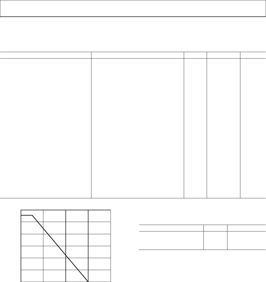
Average Output Current per Pin
3
Side 1 Output Current (I
O1
) −10 mA to +10 mA
Side 2 Output Current (I
O2
) −10 mA to +10 mA
Common-Mode Transients
4
−150 kV/s to +150 kV/s
1
V
DDI
is the input side supply voltage.
2
V
DDO
is the output side supply voltage.
3
See Figure 4 for the maximum rated current values for various ambient
temperatures.
4
Refers to the common-mode transients across the insulation barrier.
Common-mode transients exceeding the absolute maximum ratings may
cause latch-up or permanent damage.
Stresses at or above those listed under Absolute Maximum
Ratings may cause permanent damage to the product. This is a
stress rating only; functional operation of the product at these
or any other conditions above those indicated in the operational
section of this specification is not implied. Operation beyond
the maximum operating conditions for extended periods may
affect product reliability.
Table 17. Maximum Continuous Working Voltage
1
RW-16
Wide Body [SOIC_W] Package
Parameter Rating Constraint
AC Voltage
Bipolar Waveform
Basic Insulation 849 V peak 50-year minimum insulation
lifetime
Reinforced
Insulation
768 V peak Lifetime limited by package
creepage maximum approved
working voltage per IEC 60950-1
Unipolar Waveform
Basic Insulation 1698 V peak 50-year minimum insulation
lifetime
Reinforced
Insulation
885 V peak Lifetime limited by package
creepage maximum approved
working voltage per IEC 60950-1
DC Voltage
Basic Insulation 1092 V peak Lifetime limited by package
creepage maximum approved
working voltage per IEC 60950-1
Reinforced
Insulation
543 V peak Lifetime limited by package
creepage maximum approved
working voltage per IEC 60950-1
1
Refers to the continuous voltage magnitude imposed across the isolation
barrier. See the Insulation Lifetime section for more details.
Table 18. Maximum Continuous Working Voltage
1
RI-16-2
Wide Body Increased Creepage [SOIC_IC] Package
Parameter Rating Constraint
AC Voltage
Bipolar Waveform
Basic Insulation 849 V peak 50-year minimum insulation
lifetime
Reinforced
Insulation
819 V peak Lifetime limited by package
creepage maximum approved
working voltage per IEC 60950-1
Unipolar Waveform
Basic Insulation 1698 V peak 50-year minimum insulation
lifetime
Reinforced
Insulation
943 V peak Lifetime limited by package
creepage maximum approved
working voltage per IEC 60950-1
DC Voltage
Basic Insulation 1157 V peak Lifetime limited by package
creepage maximum approved
working voltage per IEC 60950-1
Reinforced
Insulation
579 V peak Lifetime limited by package
creepage maximum approved
working voltage per IEC 60950-1
1
Refers to the continuous voltage magnitude imposed across the isolation
barrier. See the Insulation Lifetime section for more details.
ESD CAUTION
Data Sheet ADuM240D/ADuM240E/ADuM241D/ADuM241E/ADuM242D/ADuM242E
Rev. A | Page 15 of 26
Truth Tables
Table 19. ADuM240D/ADuM241D/ADuM242D Truth Table (Positive Logic)
V
Ix
Input
1, 2
V
DISABLEx
Input
1, 2
V
DDI
State
2
V
DDO
State
2
Default Low (D0),
V
Ox
Output
1, 2, 3
Default High (D1),
V
Ox
Output
1, 2, 3
Test Conditions/
Comments
L L or NC Powered Powered L L Normal operation
H L or NC Powered Powered H H Normal operation
X H Powered Powered L H
Inputs disabled,
fail-safe output
X
4
X
4
Unpowered Powered L H Fail-safe output
X
4
X
4
Powered Unpowered Indeterminate Indeterminate
1
L means low, H means high, X means don’t care, and NC means not connected.
2
V
Ix
and V
Ox
refer to the input and output signals of a given channel (A, B, C, or D). V
DISABLEx
refers to the input disable signal on the same side as the V
Ix
inputs. V
DDI
and
V
DDO
refer to the supply voltages on the input and output sides of the given channel, respectively.
3
D0 is the ADuM240D0/ADuM241D0/ADuM242D0 models, and D1 is the ADuM240D1/ADuM241D1/ADuM242D1 models. See the Ordering Guide section.
4
Input pins (V
Ix
, DISABLE
x
) on the same side as an unpowered supply must be in a low state to avoid powering the device through its ESD protection circuitry.
Table 20. ADuM240E/ADuM241E/ADuM242E Truth Table (Positive Logic)
V
Ix
Input
1, 2
V
Ex
Input
1, 2
V
DDI
State
2
V
DDO
State
2
Default Low (E0),
V
Ox
Output
1, 2, 3
Default High (E1),
V
Ox
Output
1, 2, 3
Test Conditions/
Comments
L H or NC Powered Powered L L Normal operation
H H or NC Powered Powered H H Normal operation
X L Powered Powered Z Z Outputs disabled
L H or NC Unpowered Powered L H Fail-safe output
X
4
L
4
Unpowered Powered Z Z Outputs disabled
X
4
X
4
Powered Unpowered Indeterminate Indeterminate
1
L means low, H means high, X means don’t care, NC means not connected, and Z means high impedance.
2
V
Ix
and V
Ox
refer to the input and output signals of a given channel (A, B, C, or D). V
Ex
refers to the output enable signal on the same side as the V
Ox
outputs. V
DDI
and
V
DDO
refer to the supply voltages on the input and output sides of the given channel, respectively.
3
E0 is the ADuM240E0/ADuM241E0/ADuM242E0 models, and E1 is the ADuM240E1/ADuM241E1/ADuM242E1 models. See the Ordering Guide section.
4
Input pins (V
Ix
, V
Ex
) on the same side as an unpowered supply must be in a low state to avoid powering the device through its ESD protection circuitry.

ADUM240E1BRIZ

Mfr. #:
Manufacturer:
Analog Devices Inc.
Description:
Digital Isolators IC Robust Quad ISO 4:0 ch
Lifecycle:
New from this manufacturer.
Delivery:
DHL FedEx Ups TNT EMS
Payment:
T/T Paypal Visa MoneyGram Western Union