SMC5K10A thru SMC5K85A
www.vishay.com
Vishay General Semiconductor
Revision: 16-Jan-18
2
Document Number: 87742
For technical questions within your region: DiodesAmericas@vishay.com
, DiodesAsia@vishay.com, DiodesEurope@vishay.com
THIS DOCUMENT IS SUBJECT TO CHANGE WITHOUT NOTICE. THE PRODUCTS DESCRIBED HEREIN AND THIS DOCUMENT
ARE SUBJECT TO SPECIFIC DISCLAIMERS, SET FORTH AT www.vishay.com/doc?91000
Notes
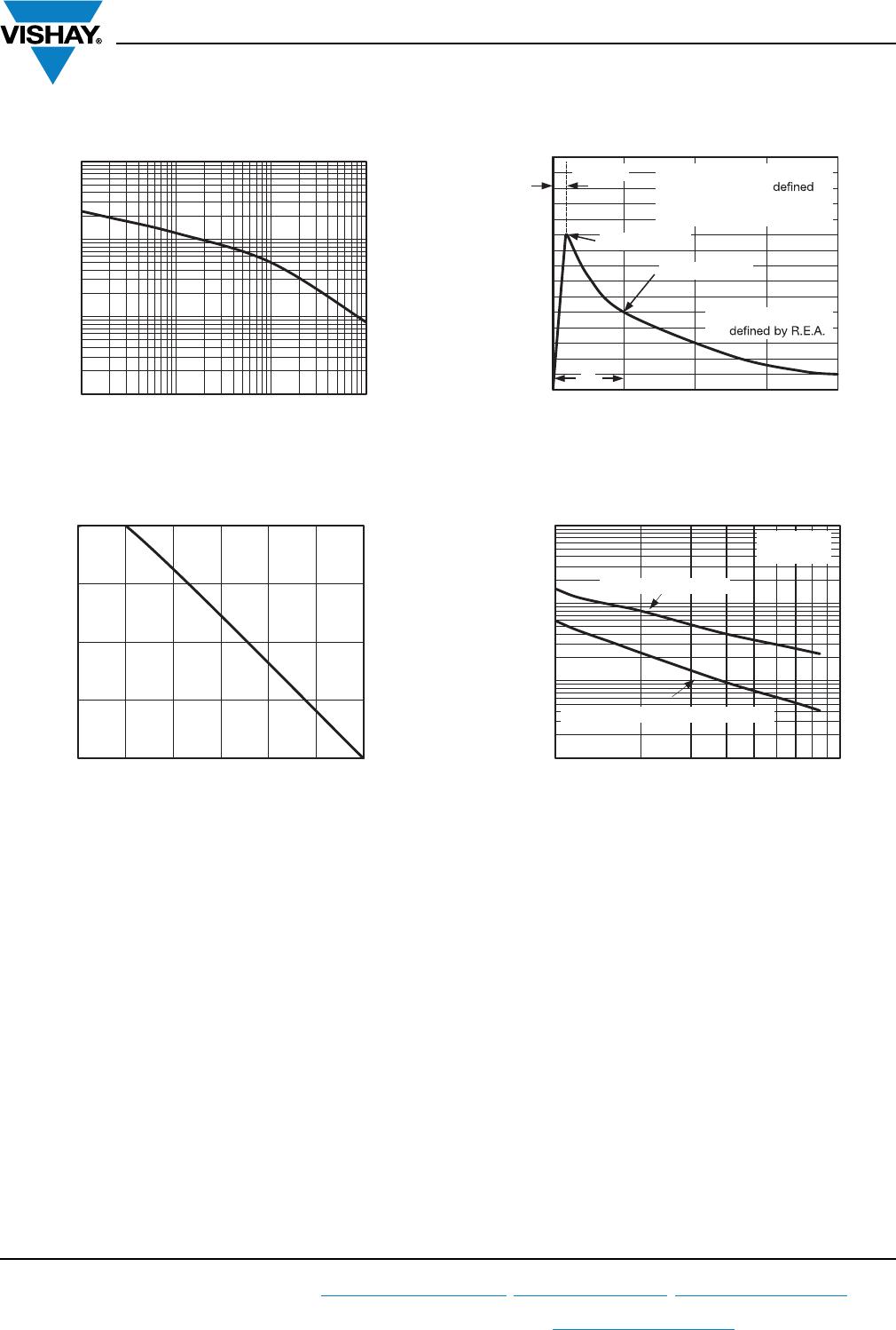
(1)
Pulse test: t
p
50 ms
(2)
Surge current waveform per fig. 3 and derated per fig.2
(3)
All terms and symbols are consistent with ANSI/IEEE C62.35
Note
(1)
AEC-Q101 qualified, available for SMC5K10A to SMC5K20A only
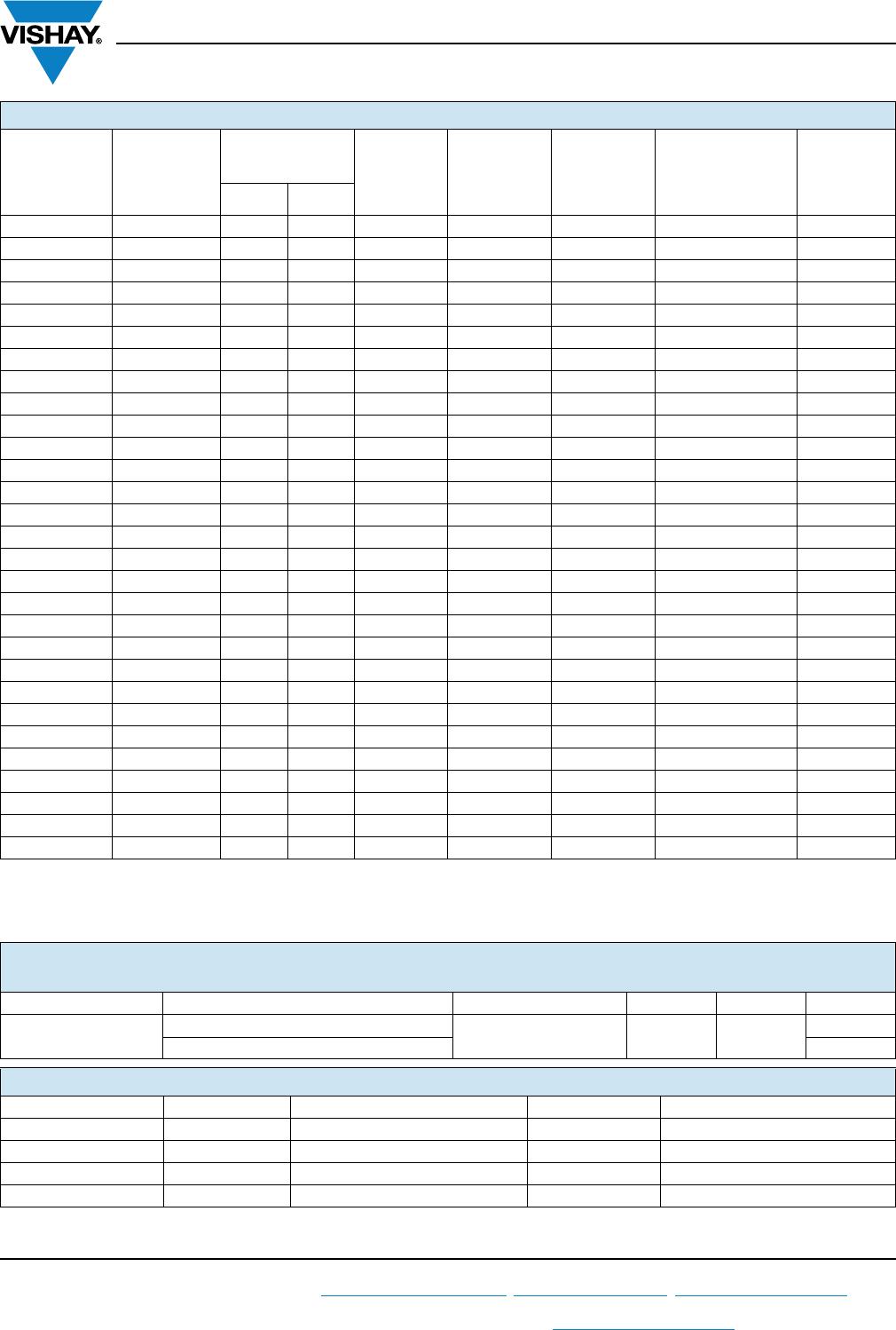
ELECTRICAL CHARACTERISTICS (T
A
= 25 °C unless otherwise noted)
DEVICE TYPE
DEVICE
MARKING
CODE
BREAKDOWN
VOLTAGE
V
BR
(1)
(V) AT I
T
TEST
CURRENT
I
T
(mA)
STAND-OFF
VOLTAGE
V
WM
(V)
MAXIMUM
REVERSE
LEAKAGE
AT V
WM
I
D
(μA)
MAX. PEAK PULSE
SURGE CURRENT
I
PPM
(2)
(A)
MAXIMUM
CLAMPING
VOLTAGE
AT I
PPM
V
C
(V)
MIN. MAX.
SMC5K10A 5GDX 11.1 12.3 1.0 10 10.0 294 17.0
SMC5K12A 5GEE 13.3 14.7 1.0 12 5.0 251 19.9
SMC5K13A 5GEG 14.4 15.9 1.0 13 2.0 233 21.5
SMC5K14A 5GEK 15.6 17.2 1.0 14 2.0 216 23.2
SMC5K15A 5GEM 16.7 18.5 1.0 15 2.0 205 24.4
SMC5K16A 5GEP 17.8 19.7 1.0 16 2.0 192 26.0
SMC5K17A 5GER 18.9 20.9 1.0 17 2.0 181 27.6
SMC5K18A 5GET 20.0 22.1 1.0 18 2.0 171 29.2
SMC5K20A 5GEV 22.2 24.5 1.0 20 2.0 154 32.4
SMC5K22A 5GEX 24.4 26.9 1.0 22 1.0 141 35.5
SMC5K24A 5GEZ 26.7 29.5 1.0 24 1.0 129 38.9
SMC5K26A 5GFE 28.9 31.9 1.0 26 1.0 119 42.1
SMC5K28A 5GFG 31.1 34.4 1.0 28 1.0 110 45.4
SMC5K30A 5GFK 33.3 36.8 1.0 30 1.0 103 48.4
SMC5K33A 5GFM 36.7 40.6 1.0 33 1.0 93.8 53.3
SMC5K36A 5GFP 40.0 44.2 1.0 36 1.0 86.1 58.1
SMC5K40A 5GFR 44.4 49.1 1.0 40 1.0 77.5 64.5
SMC5K43A 5GFT 47.8 52.8 1.0 43 1.0 72.0 69.4
SMC5K45A 5GFV 50.0 55.3 1.0 45 1.0 68.8 72.7
SMC5K48A 5GFX 53.3 58.9 1.0 48 1.0 64.6 77.4
SMC5K51A 5GFZ 56.7 62.7 1.0 51 1.0 60.7 82.4
SMC5K54A 5GGE 60.0 66.3 1.0 54 1.0 57.4 87.1
SMC5K58A 5GGG 64.4 71.2 1.0 58 1.0 53.4 93.6
SMC5K60A 5GGK 66.7 73.7 1.0 60 1.0 51.7 96.8
SMC5K64A 5GGM 71.1 78.6 1.0 64 1.0 48.5 103
SMC5K70A 5GGP 77.8 86.0 1.0 70 1.0 44.2 113
SMC5K75A 5GGR 83.3 92.1 1.0 75 1.0 41.3 121
SMC5K78A 5GGT 86.7 95.8 1.0 78 1.0 39.7 126
SMC5K85A 5GGV 94.4 104 1.0 85 1.0 36.5 137
IMMUNITY TO STATIC ELECTRICAL DISCHARGE TO THE FOLLOWING STANDARDS
(T
A
= 25 °C unless otherwise noted)
STANDARD TEST TYPE TEST CONDITIONS SYMBOL CLASS VALUE
IEC 61000-4-2
Human body model (contact mode)
C = 150 pF, R = 330 ESD 4
> 8 kV
Human body model (air discharge mode) > 15 kV
ORDERING INFORMATION (Example)
PREFERRED P/N UNIT WEIGHT (g) PREFERRED PACKAGE CODE BASE QUANTITY DELIVERY MODE
SMC5K10A-M3/H 0.257 H 850 7" diameter plastic tape and reel
SMC5K10A-M3/I 0.257 I 3500 13" diameter plastic tape and reel
SMC5K10AHM3/H
(1)
0.257 H 850 7" diameter plastic tape and reel
SMC5K10AHM3/I
(1)
0.257 I 3500 13" diameter plastic tape and reel