© Semiconductor Components Industries, LLC, 2009
December, 2009 − Rev. 0
1 Publication Order Number:
AMIS−30522/D
AMIS-30522, NCV70522
Micro-Stepping Motor Driver
Introduction
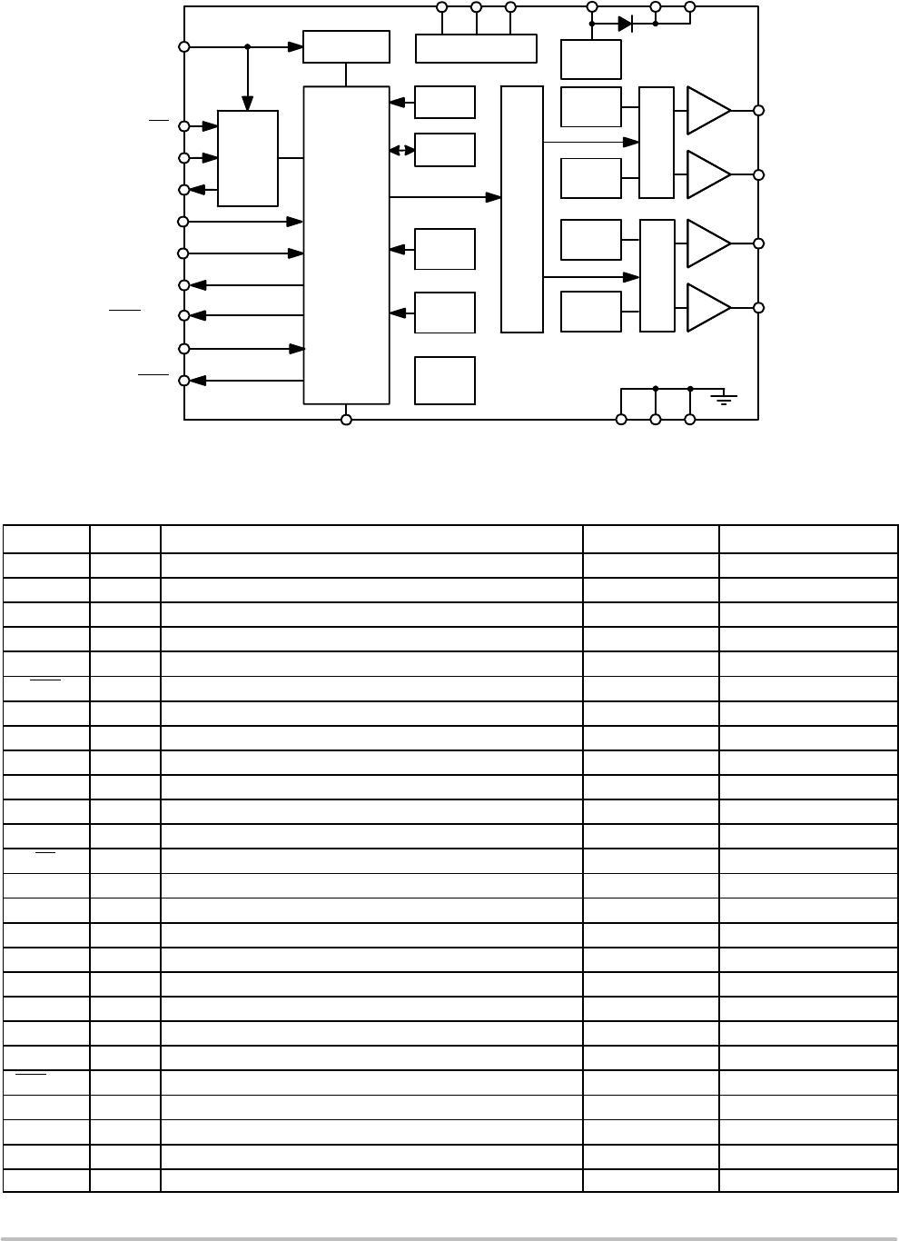
The AMIS−30522/NCV70522 is a micro−stepping stepper motor
driver for bipolar stepper motors. The chip is connected through I/O
pins and a SPI interface with an external microcontroller. The
AMIS−30522/NCV70522 contains a current−translation table. It takes
the next micro−step depending on the clock signal on the “NXT” input
pin and the status of the “DIR” (= direction) register or input pin. The
chip provides a so−called “Speed and Load Angle” output. This allows
the creation of stall detection algorithms and control loops based on
load−angle to adjust torque and speed. It is using a proprietary PWM
algorithm for reliable current control.
The AMIS−30522/NCV70522 is implemented in I
2
T100
technology, enabling both high voltage analog circuitry and digital
functionality on the same chip. The chip is fully compatible with the
automotive voltage requirements.
The 522 is ideally suited for general purpose stepper motor
applications in the automotive, industrial, medical and marine
environment. The AMIS−30522 is intended for use in industrial
applications. The NCV70522 version is qualified for use in
automotive applications.
Features
• Dual H−Bridge for 2 Phase Stepper Motors
• Programmable Peak−Current up to 1.2 A Continuous (1.5 A Short
Time), Using a 5−Bit Current DAC
• On−Chip Current Translator
• SPI Interface
• Speed and Load−Angle Output
• 7 Step Modes from Full−Step up to 32 Micro−Steps
• Fully Integrated Current−Sense
• PWM Current Control with Automatic Selection of Fast and Slow
Decay
• Low EMC PWM with Selectable Voltage Slopes
• Active Fly−back Diodes
• Full Output Protection and Diagnosis
• Thermal Warning and Shutdown
• Digital IO’s Compatible with 5 V and 3.3 V Microcontrollers
• Integrated 5 V Voltage Regulator to Supply an External
Microcontroller
• Integrated Reset Function to Reset External Microcontroller
• Integrated Watchdog Function
• NCV Prefix for Automotive and Other Applications Requiring Site
and Control Changes
• These are Pb−Free Devices*
*For additional information on our Pb−Free strategy and soldering details, please
download the ON Semiconductor Soldering and Mounting Techniques
Reference Manual, SOLDERRM/D.
http://onsemi.com
See detailed ordering and shipping information in the package
dimensions section on page 27 of this data sheet.
ORDERING INFORMATION
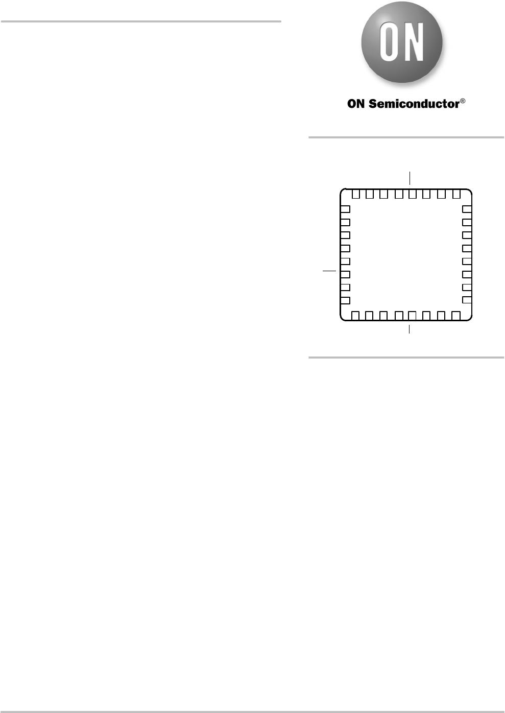
1
2
3
5
4
6
7
8
24
23
22
20
21
19
18
17
910111213141516
32 31 30 29 28 27 26 25
DI
GND GND
MOTYN
CLK
DIR
NXT
SLA
GND
GND
GND
MOTYN
MOTXN
MOTXN
ERR
CPN
CPP
VCP
CLR
VBB
MOTYP
MOTYP
CS
VDD
DO
TSTO
VBB
MOTXP
MOTXP
PINOUT
AMIS−30522/
NCV70522
POR/WD