© 2006 Microchip Technology Inc. DS21204E-page 13
25AA040/25LC040/25C040
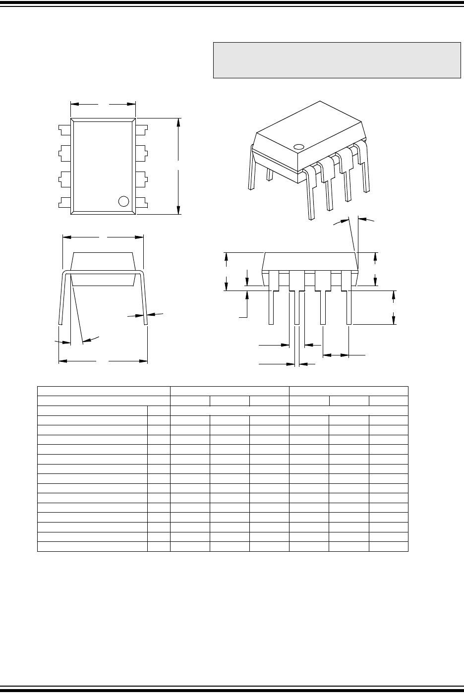
8-Lead Plastic Dual In-line (P) – 300 mil (PDIP)
B1
B
A1
A
L
A2
p
α
E
eB
β
c
E1
n
D
1
2
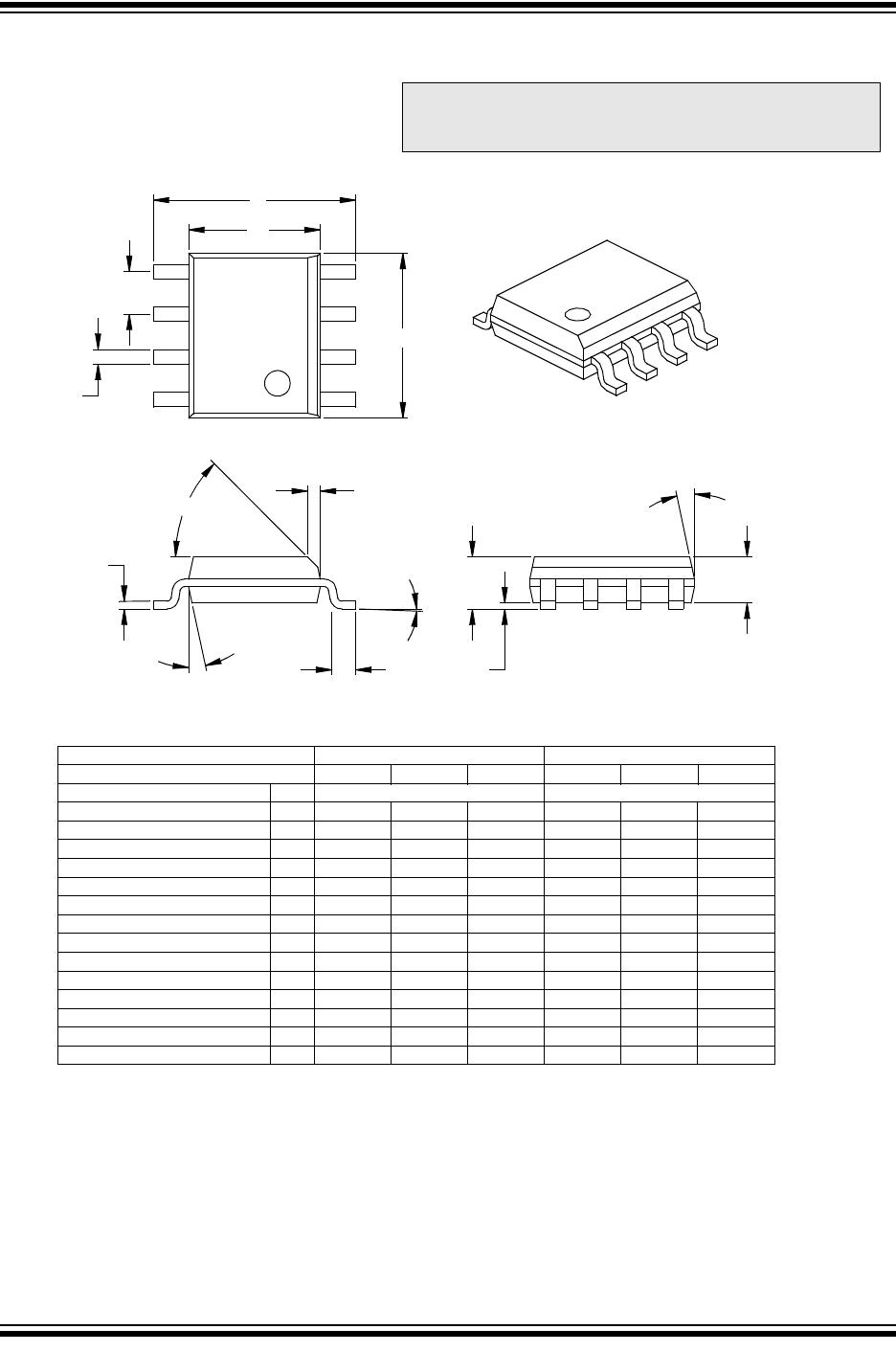
Units INCHES* MILLIMETERS
Dimension Limits MIN NOM MAX MIN NOM MAX
Number of Pins
n
88
Pitch
p
.100 2.54
Top to Seating Plane A .140 .155 .170 3.56 3.94 4.32
Molded Package Thickness A2 .115 .130 .145 2.92 3.30 3.68
Base to Seating Plane A1 .015 0.38
Shoulder to Shoulder Width E .300 .313 .325 7.62 7.94 8.26
Molded Package Width E1 .240 .250 .260 6.10 6.35 6.60
Overall Length D .360 .373 .385 9.14 9.46 9.78
Tip to Seating Plane L .125 .130 .135 3.18 3.30 3.43
Lead Thickness
c
.008 .012 .015 0.20 0.29 0.38
Upper Lead Width B1 .045 .058 .070 1.14 1.46 1.78
Lower Lead Width B .014 .018 .022 0.36 0.46 0.56
Overall Row Spacing § eB .310 .370 .430 7.87 9.40 10.92
Mold Draft Angle Top
α
51015 51015
Mold Draft Angle Bottom
β
51015 51015
* Controlling Parameter
Notes:
Dimensions D and E1 do not include mold flash or protrusions. Mold flash or protrusions shall not exceed .010” (0.254mm) per side.
JEDEC Equivalent: MS-001
Drawing No. C04-018
§ Significant Characteristic
Note: For the most current package drawings, please
see the Microchip Packaging Specification located
at http://www.microchip.com/packaging
25AA040/25LC040/25C040
DS21204E-page 14 © 2006 Microchip Technology Inc.
8-Lead Plastic Small Outline (SN) – Narrow, 150 mil (SOIC)
Foot Angle
φ
048048
1512015120
β
Mold Draft Angle Bottom
1512015120
α
Mold Draft Angle Top
0.510.420.33.020.017.013BLead Width
0.250.230.20.010.009.008
c
Lead Thickness
0.760.620.48.030.025.019LFoot Length
0.510.380.25.020.015.010hChamfer Distance
5.004.904.80.197.193.189DOverall Length
3.993.913.71.157.154.146E1Molded Package Width
6.206.025.79.244.237.228EOverall Width
0.250.180.10.010.007.004A1Standoff §
1.551.421.32.061.056.052A2Molded Package Thickness
1.751.551.35.069.061.053AOverall Height
1.27
.050
p
Pitch
88
n
Number of Pins
MAXNOMMINMAXNOMMINDimension Limits
MILLIMETERSINCHES*Units
2
1
D
n
p
B
E
E1
h
L
β
c
45°
φ
A2
α
A
A1
* Controlling Parameter
Notes:
Dimensions D and E1 do not include mold flash or protrusions. Mold flash or protrusions shall not exceed .010” (0.254mm) per side.
JEDEC Equivalent: MS-012
Drawing No. C04-057
§ Significant Characteristic
Note: For the most current package drawings, please
see the Microchip Packaging Specification located
at http://www.microchip.com/packaging
© 2006 Microchip Technology Inc. DS21204E-page 15
25AA040/25LC040/25C040
8-Lead Plastic Thin Shrink Small Outline (ST) – 4.4 mm (TSSOP)
E
E1
D
e
n
b
2
1
c
L
A
A1
A2
ϕ
β
α
MILLIMETERS*
MIN NOM
MAX
1.20
1.05
0.15
4.50
3.10
0.75
0.20
0.30
8
1.00
4.40
3.00
0.60
0.80
0.05
4.30
2.90
0.45
0.09
0.19
INCHES
MIN NOM
MAX
8
.039
.173
.118
.024
.047
.041
.006
.177
.122
.030
.008
.012
.031
.002
.169
.114
.018
.004
.007
.026 BSC
0.65 BSC
.252 BSC
6.40 BSC
12° REF
12° REF
12° REF
12° REF
Units
Dimension Limits
Number of Pins
Pitch
Overall Height
Molded Package Thickness
Standoff
Overall Width
Molded Package Width
Molded Package Length
Foot Length
Foot Angle
Lead Thickness
Lead Width
Mold Draft Angle Top
Mold Draft Angle Bottom
*Controlling Parameter
Notes:
1. Dimension D and E1 do not include mold flash or protrusions. Mold flash or protrusions shall not exceed
.005" (0.127mm) per side.
BSC: Basic Dimension. Theoretically exact value shown without tolerances.
See ASME Y14.5M
REF: Reference Dimension, usually without tolerance, for information purposes only.
See ASME Y14.5M
Drawing No. C04-086 Revised 7-25-06
n
e
A
A2
A1
E
E1
D
L
ϕ
c
b
α
β
Note: For the most current package drawings, please
see the Microchip Packaging Specification located
at http://www.microchip.com/packaging

25AA040T-I/SN

Mfr. #:
Manufacturer:
Microchip Technology
Description:
EEPROM 512x8 - 1.8V
Lifecycle:
New from this manufacturer.
Delivery:
DHL FedEx Ups TNT EMS
Payment:
T/T Paypal Visa MoneyGram Western Union