1
DATASHEET
64k, 8k x 8-Bit 5 Volt, Byte Alterable EEPROM
X28HC64
The X28HC64 is an 8k x 8 EEPROM, fabricated with Intersil’s
proprietary, high performance, floating gate CMOS technology.
Like all Intersil programmable nonvolatile memories, the
X28HC64 is a 5V only device. It features the JEDEC approved
pinout for byte-wide memories, compatible with industry
standard RAMs.
The X28HC64 supports a 64-byte page write operation, effectively
providing a 32µs/byte write cycle, and enabling the entire
memory to be typically written in 0.25 seconds. The X28HC64
also features DATA
Polling and Toggle Bit Polling, two methods
providing early end of write detection. In addition, the X28HC64
includes a user-optional software data protection mode that
further enhances Intersil’s hardware write protect capability.
Intersil EEPROMs are designed and tested for applications
requiring extended endurance. Inherent data retention is
greater than 100 years.
Features
70ns access time
Simple byte and page write
-Single 5V supply
-No external high voltages or V
P-P
control circuits
-Self-timed
- No erase before write
- No complex programming algorithms
- No overerase problem
•Low power CMOS
- 40mA active current maximum
200µA standby current maximum
Fast write cycle times
- 64-byte page write operation
- Byte or page write cycle: 2ms typical
- Complete memory rewrite: 0.25s typical
- Effective byte write cycle time: 32µs typical
Software data protection
•End of write detection
- DATA polling
-Toggle bit
High reliability
- Endurance: 100,000 cycles
- Data retention: 100 years
•JEDEC approved byte-wide pinout
Pb-free available (RoHS compliant)
Pin Configurations
X28HC64
(28 LD PDIP, SOIC)
TOP VIEW
X28HC64
(32 LD PLCC)
TOP VIEW
NC
A
12
A
7
A
6
A
5
A
4
A
3
A
2
A
1
A
0
I/O
0
I/O
1
I/O
2
V
SS
1
2
3
4
5
6
7
8
9
10
11
12
13
14
28
27
26
25
24
23
22
21
20
19
18
17
16
15
V
CC
WE
NC
A
8
A
9
A
11
OE
A
10
CE
I/O
7
I/O
6
I/O
5
I/O
4
I/O
3
X28HC64
A
6
A
5
A
4
A
3
A
2
A
1
A
0
NC
I/O
0
A
8
A
9
A
11
NC
OE
A
10
CE
I/O
7
I/O
6
4 3 2 1 32 31 30
14 15 16 17 18 19 20
5
6
7
8
9
10
11
12
13
29
28
27
26
25
24
23
22
21
A
7
I/O
1
I/O
2
V
SS
I/O
3
I/O
4
I/O
5
A
12
NC
V
CC
WE
NC
X28HC64
NC
NC
CAUTION: These devices are sensitive to electrostatic discharge; follow proper IC Handling Procedures.
1-888-INTERSIL or 1-888-468-3774
| Copyright Intersil Americas LLC 2005, 2006, 2009, 2015, 2016. All Rights Reserved
Intersil (and design) is a trademark owned by Intersil Corporation or one of its subsidiaries.
All other trademarks mentioned are the property of their respective owners.
June 27, 2016
FN8109.4
X28HC64
2
FN8109.4
June 27, 2016
Submit Document Feedback
Ordering Information
PART NUMBER PART MARKING
TEMPERATURE
RANGE (°C)
ACCESS TIME
(ns) PACKAGE
PKG.
DWG. #
X28HC64J-70 (Notes 1, 6)
(No longer available, recommended
replacement: X28HC64JZ-70)
X28HC64J-70 CY 0 to +70 70 32 Ld PLCC N32.45x55
X28HC64JIZ-70 (Notes 1
, 4, 6) X28HC64JI-70 ZCY -40 to +85 32 Ld PLCC (RoHS Compliant) N32.45x55
X28HC64JZ-70 (Notes 1
, 4, 6) X28HC64J-70 ZCY 0 to +70 32 Ld PLCC (RoHS Compliant) N32.45x55
X28HC64SIZ-70 (Notes 4
, 6) X28HC64SI-70 CYZ -40 to +85 28 Ld SOIC (300 mil) (RoHS
Compliant)
M28.3
X28HC64SZ-70 (Notes 4
, 6) X28HC64S-70 CYZ 0 to +70 28 Ld SOIC (300 mil) (RoHS
Compliant)
M28.3
X28HC64J-90 (Notes 1
, 6)
(No longer available, recommended
replacement: X28HC64JIZ-90)
X28HC64J-90 CY 0 to +70 90 32 Ld PLCC N32.45x55
X28HC64JI-90 (Notes 1
, 3, 6)
(No longer available, recommended
replacement: X28HC64JIZ-90)
X28HC64JI-90 CY -40 to +85 32 Ld PLCC N32.45x55
X28HC64JIZ-90 (Notes 1
, 4, 6) X28HC64JI-90 ZCY -40 to +85 32 Ld PLCC (RoHS Compliant) N32.45x55
X28HC64PIZ-90 (Notes 4
, 5) X28HC64PI-90 CYZ -40 to +85 28 Ld PDIP (RoHS Compliant) E28.6
X28HC64PZ-90 (Notes 4
, 5) X28HC64P-90 CYZ 0 to +70 28 Ld PDIP (RoHS Compliant) E28.6
X28HC64J-12 (Notes 1
, 6)
(No longer available, recommended
replacement: X28HC64JZ-12)
X28HC64J-12 CY 0 to +70 120 32 Ld PLCC N32.45x55
X28HC64JI-12 (Notes 1
, 6)
(No longer available, recommended
replacement: X28HC64JIZ-12)
X28HC64JI-12 CY -40 to +85 32 Ld PLCC N32.45x55
X28HC64JIZ-12 (Notes 1
, 4, 6) X28HC64JI-12 ZCY -40 to +85 32 Ld PLCC (RoHS Compliant) N32.45x55
X28HC64JZ-12* (Notes 1, 4, 6) X28HC64J-12 ZCY 0 to +70 32 Ld PLCC (RoHS Compliant) N32.45x55
X28HC64PIZ-12 (Notes 4
, 5) X28HC64PI-12 CYZ -40 to +85 28 Ld PDIP (RoHS Compliant) E28.6
X28HC64PZ-12 (Notes 4
, 5) X28HC64P-12 CYZ 0 to +70 28 Ld PDIP (RoHS Compliant) E28.6
X28HC64SIZ-12 (Notes 2
, 4, 6) X28HC64SI-12 CYZ -40 to +85 28 Ld SOIC (300 mil) (RoHS
Compliant)
M28.3
X28HC64SZ-12 (Notes 4
, 6) X28HC64S-12 CYZ 0 to +70 28 Ld SOIC (300 mil) (RoHS
Compliant)
M28.3
NOTES:
1. Add “T1” suffix for 750 unit tape and reel option.
2. Add “T1” suffix for 1000 unit tape and reel option.
3. Add “T2” suffix for 750 unit tape and reel option.
4. These Intersil Pb-free plastic packaged products employ special Pb-free material sets, molding compounds/die attach materials, and 100% matte
tin plate plus anneal (e3 termination finish, which is RoHS compliant and compatible with both SnPb and Pb-free soldering operations). Intersil Pb-
free products are MSL classified at Pb-free peak reflow temperatures that meet or exceed the Pb-free requirements of IPC/JEDEC J STD-020.
5. Pb-free PDIPs can be used for through hole wave solder processing only. They are not intended for use in Reflow solder processing applications.
6. For Moisture Sensitivity Level (MSL), please see product information page for X28HC64
. For more information on MSL, please see tech brief TB363.
X28HC64
3
FN8109.4
June 27, 2016
Submit Document Feedback
Device Operation
Read
Read operations are initiated by both OE and CE LOW. The read
operation is terminated by either CE
or OE returning HIGH. This
two line control architecture eliminates bus contention in a
system environment. The data bus will be in a high impedance
state when either OE
or CE is HIGH.
Write
Write operations are initiated when both CE and WE are LOW and
OE is HIGH. The X28HC64 supports both a CE and WE controlled
write cycle. That is, the address is latched by the falling edge of
either CE
or WE, whichever occurs last. Similarly, the data is
latched internally by the rising edge of either CE or WE, whichever
occurs first. A byte write operation, once initiated, will
automatically continue to completion, typically within 2ms.
Page Write Operation
The page write feature of the X28HC64 allows the entire memory
to be written in 0.25 seconds. Page write allows two to sixty-four
bytes of data to be consecutively written to the X28HC64 prior to
the commencement of the internal programming cycle. The host
can fetch data from another device within the system during a
page write operation (change the source address), but the page
address (A
6
through A
12
) for each subsequent valid write cycle to
the part during this operation must be the same as the initial page
address.
The page write mode can be initiated during any write operation.
Following the initial byte write cycle, the host can write an
additional one to sixty-three bytes in the same manner. Each
successive byte load cycle, started by the WE
HIGH to LOW
transition, must begin within 100µs of the falling edge of the
preceding WE
. If a subsequent WE HIGH to LOW transition is not
detected within 100µs, the internal automatic programming
cycle will commence. There is no page write window limitation.
Effectively the page write window is infinitely wide, so long as the
host continues to access the device within the byte load cycle
time of 100µs.
Write Operation Status Bits
The X28HC64 provides the user two write operation status bits.
These can be used to optimize a system write cycle time. The
status bits are mapped onto the I/O bus as shown in Figure 2.
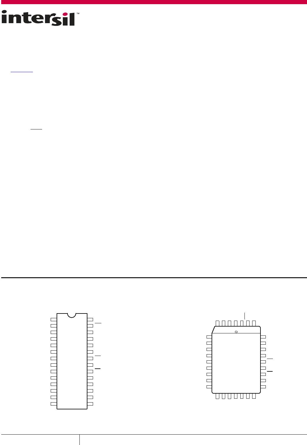
Pin Descriptions
SYMBOL DESCRIPTION
A
0
-A
12
Address Inputs. The Address inputs
select an 8-bit memory location
during a read or write operation.
I/O
0
-I/O
7
Data Input/Output. Data is written
to or read from the X28HC64
through the I/O pins.
WE
Write Enable. The Write Enable
input controls the writing of data to
the X28HC64.
CE
Chip Enable. The Chip Enable input
must be LOW to enable all
read/write operations. When CE is
HIGH, power consumption is
reduced.
OE
Output Enable. The Output Enable
input controls the data output
buffers and is used to initiate read
operations.
V
CC
+5V
V
SS
Ground
NC No Connect
Block Diagram
FIGURE 1. BLOCK DIAGRAM
X BUFFERS
LATCHES AND
DECODER
I/O BUFFERS
AND LATCHES
Y BUFFERS
LATCHES
DECODER
CONTROL
LOGIC AND
TIMING
65,536-BIT
EEPROM
ARRAY
I/O
0
–I/O
7
DATA INPUTS/OUTPUTS
CE
OE
V
CC
V
SS
A
0
–A
12
WE
ADDRESS
INPUTS
AND
5TBDP 43210I/O
RESERVED
TOGGLE BIT
DATA
POLLING
FIGURE 2. STATUS BIT ASSIGNMENT

X28HC64JIZ-90

Mfr. #:
Manufacturer:
Renesas / Intersil
Description:
EEPROM 8K X 8 EEPROM CMOS 3
Lifecycle:
New from this manufacturer.
Delivery:
DHL FedEx Ups TNT EMS
Payment:
T/T Paypal Visa MoneyGram Western Union

Products related to this Datasheet