NPH10S Series
Isolated 10W Single Output DC/DC Converters
KDC_NPH10SC.J03 Page 5 of 8
www.murata-ps.com/suppor t
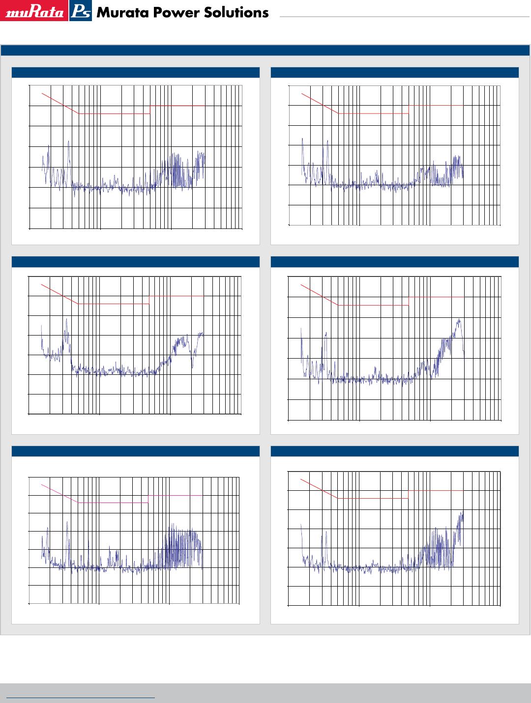
EMC FILTERING AND SPECTRA
FILTERING
The module includes a basic level of filtering, sufficient for many applications. Where lower noise levels are desired, filters can easily be added to achieve any required
noise performance.
A DC/DC converter generates noise in two principle forms: that which is radiated from its body and that conducted on its external connections. There are three separate
modes of conducted noise: input differential, output differential and input-output.
This last appears as common mode at the input and the output, and cannot therefore be removed by filtering at the input or output alone. The first level of filtering is to
connect a capacitor between input and output returns, to reduce this form of noise. It typically contains high harmonics of the switching frequency, which tend to appear
as spikes on surrounding circuits. The voltage rating of this capacitor must match the required isolation voltage. (Due to the great variety in isolation voltage and required
noise performance, this capacitor has not been included within the converter.)
Input ripple is a voltage developed across the internal Input decoupling capacitor. It is therefore measured with a defined supply source impedance. Although simple
series inductance will provide filtering, on its own it can degrade the stability. A shunt capacitor is therefore recommended across the converter input terminals, so that it
is fed from a low impedance.
If no filtering is required, the inductance of long supply wiring could also cause a problem, requiring an input decoupling capacitor for stability. An electrolytic will perform
well in these situations. The input-output filtering is performed by the common-mode choke on the primary. This could be placed on the output, but would then degrade
the regulation and produce less benefit for a given size, cost, and power loss.
Radiated noise is present in magnetic and electrostatic forms. The latter is suppressed by the metal case, which is connected to the output return, typically a zero-volt
point. Thanks to the small size of these units, neither form of noise will be radiated “efficiently”, so will not normally cause a problem. Any question of this kind usually
better repays attention to conducted signals.
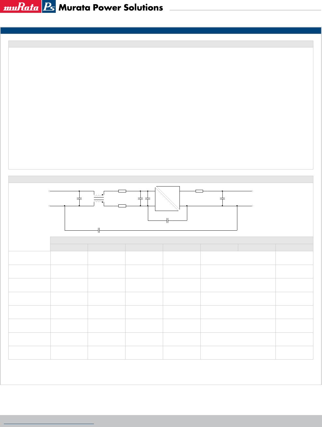
EMC FILTER AND VALUES TO OBTAIN SPECTRA AS SHOWN
Component reference
C1 C2 C3 C4 L1 L2 L3
NPH10S2403
10μF 100V 47μF 63V 2.2μF 63V 10μF 25V
MPS 18R333C
33μH 2A
MPS 18R472C
4.7μH 5.35A
NPH10S2405
10μF 100V 47μF 63V 2.2μF 63V 10μF 25V
MPS 18R333C
33μH 2A
MPS 18R103C
10μH 3.45A
NPH10S2412
10μF 100V Not required 470nF 63V 10μF 25V
MPS 18R333C
33μH 2A
MPS 18R333C
33μH 2.00A
NPH10S2415
10μF 100V 10μF 63V Not required 10μF 25V
MPS 18R473C
47μH 1.65A
MPS 18R333C
33μH 2.00A
NPH10S4803
10μF 100V 47μF 100V 220nF 100V 10μF 25V
MPS 18R104C
100μH 1.2A
MPS 18R472C
4.7μH 5.35A
NPH10S4805
10μF 100V 47μF 100V 220nF 100V 10μF 25V
MPS 18R104C
100μH 1.2A
MPS 18R103C
10μH 3.45A
NPH10S4812
10μF 100V Not required 470nF 100V 10μF 25V
MPS 18R104C
100μH 1.2A
MPS 18R333C
33μH 2.00A
NPH10S4815
10μF 100V Not required 470nF 100V 10μF 25V
MPS 18R104C
100μH 1.2A
MPS 18R333C
33μH 2.00A
C1, C2 & C4 : Electrolytic capacitors
C3 : Polyester or ceramic capacitor
EMC Spectra red limit line is EN 55022 curve B Quasi-peak average limit.
$
O'7"$:SBUFE
N)
"
-
-
$
%$
%$
-
O'7"$:SBUFE
$
$