31
COMMERCIAL AND INDUSTRIAL
TEMPERATURE RANGES
IDT72V3640/50/60/70/80/90 3.3V HIGH DENSITY SUPERSYNC II
TM
36-BIT FIFO
1,024 x 36, 2,048 x 36, 4,096 x 36, 8,192 x 36, 16,384 x 36 and 32,768 x 36
NOTES:
1. Retransmit setup is complete after OR returns LOW.
2. No more than D - 2 words may be written to the FIFO between Reset (Master or Partial) and Retransmit setup. Therefore, IR will be LOW throughout the Retransmit setup procedure.
D = 1,025 for the IDT72V3640, 2,049 for the IDT72V3650, 4,097 for the IDT72V3660, 8,193 for the IDT72V3670, 16,385 for the IDT72V3680 and 32,769 for the IDT72V3690.
3. OE = LOW.
4. W1, W2, W3 = first, second and third words written to the FIFO after Master Reset.
5. There must be at least two words written to the FIFO before a Retransmit operation can be invoked.
6. RM is set HIGH during MRS.
Figure 12. Retransmit Timing (FWFT Mode)
t
REF
t
RTS
t
ENH
4667 drw17
t
ENS
W
x
WCLK
RCLK
REN
RT
OR
PAF
HF
PAE
Q
0
- Q
n
t
SKEW2
12
1
t
PAFS
t
HF
t
PAES
t
REF
W
x+1
2
W
2
t
ENH
t
RTS
WEN
t
ENS
W
1
t
ENS
(4)
3
4
t
ENH
W
3
t
A
t
A
t
A
W
4
t
A
(4)
(4)
32
COMMERCIAL AND INDUSTRIAL
TEMPERATURE RANGES
IDT72V3640/50/60/70/80/90 3.3V HIGH DENSITY SUPERSYNC II
TM
36-BIT FIFO
1,024 x 36, 2,048 x 36, 4,096 x 36, 8,192 x 36, 16,384 x 36 and 32,768 x 36
NOTES:
1. If the part is empty at the point of Retransmit, the empty flag (EF) will be updated based on RCLK (Retransmit clock cycle), valid data will also appear on the output.
2. OE = LOW.
3. W1 = first word written to the FIFO after Master Reset, W2 = second word written to the FIFO after Master Reset.
4. No more than D - 2 may be written to the FIFO between Reset (Master or Partial) and Retransmit setup. Therefore, FF will be HIGH throughout the Retransmit setup procedure.
D = 1,024 for IDT72V3640, 2,048 for IDT72V3650, 4,096 for IDT72V3660, 8,192 for IDT72V3670, 16,384 for the IDT72V3680 and 32,768 for the IDT72V3690.
5. There must be at least two words written to the FIFO before a Retransmit operation can be invoked.
6. RM is set LOW during MRS.
Figure 13. Zero Latency Retransmit Timing (IDT Standard Mode)
t
RTS
t
ENH
4667 drw18
t
A
t
ENS
W
x
WCLK
RCLK
REN
RT
EF
PAF
HF
PAE
Q
0
- Q
n
t
SKEW2
12
1
W
3
(3)
t
PAFS
t
HF
t
PAES
W
x+1
2
W
4
WEN
t
ENS
t
ENH
t
A
t
A
3
t
A
t
A
W
1
(3)
W
2
(3)
33
COMMERCIAL AND INDUSTRIAL
TEMPERATURE RANGES
IDT72V3640/50/60/70/80/90 3.3V HIGH DENSITY SUPERSYNC II
TM
36-BIT FIFO
1,024 x 36, 2,048 x 36, 4,096 x 36, 8,192 x 36, 16,384 x 36 and 32,768 x 36
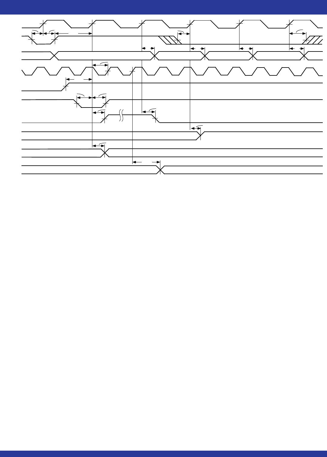
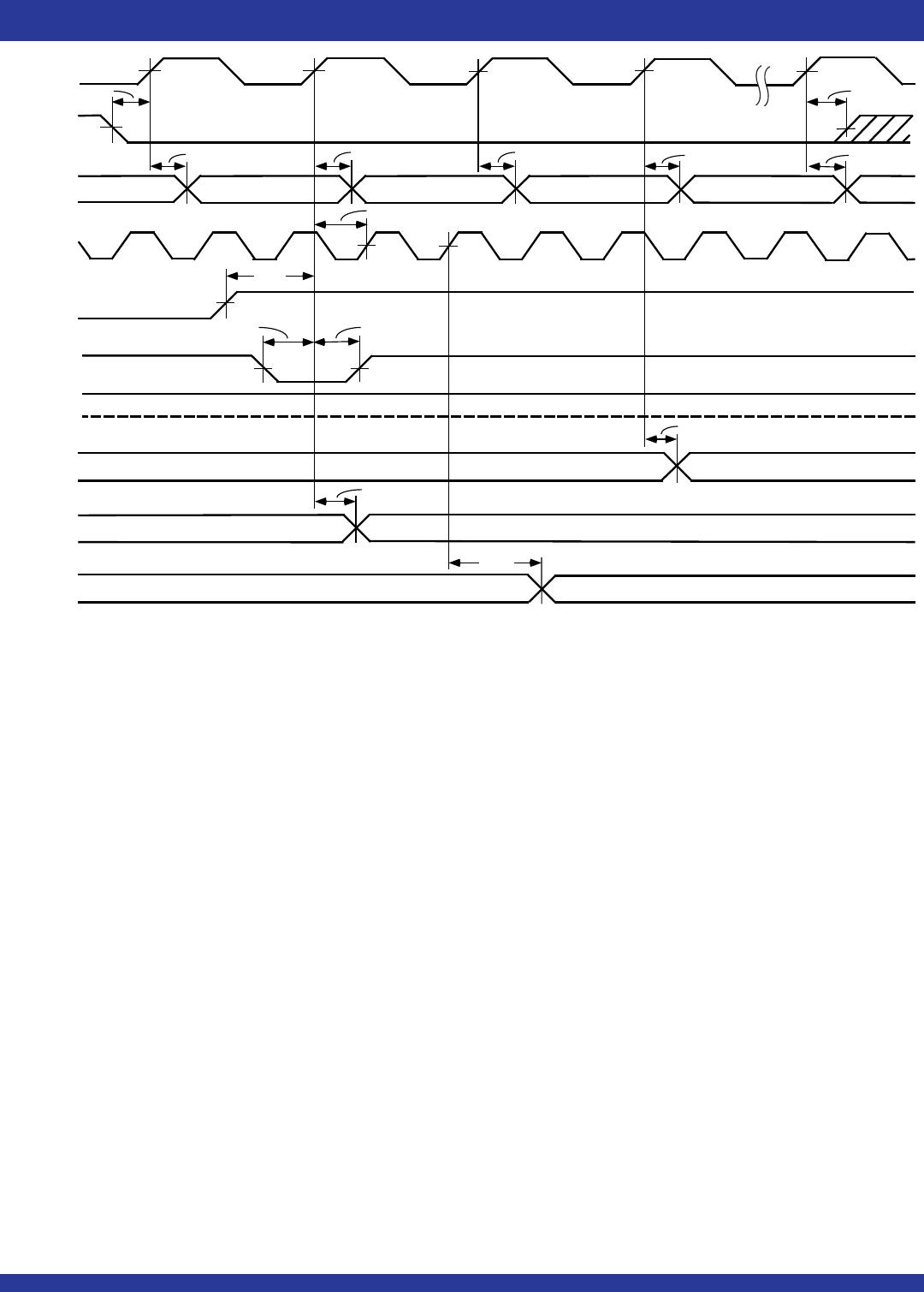
Figure 15. Serial Loading of Programmable Flag Registers (IDT Standard and FWFT Modes)
NOTE:
1. X = 9 for the IDT72V3640, X = 10 for the IDT72V3650, X = 11 for the IDT72V3660, X = 12 for the IDT72V3670, X = 13 for the IDT72V3680 and X = 14 for the IDT72V3690.
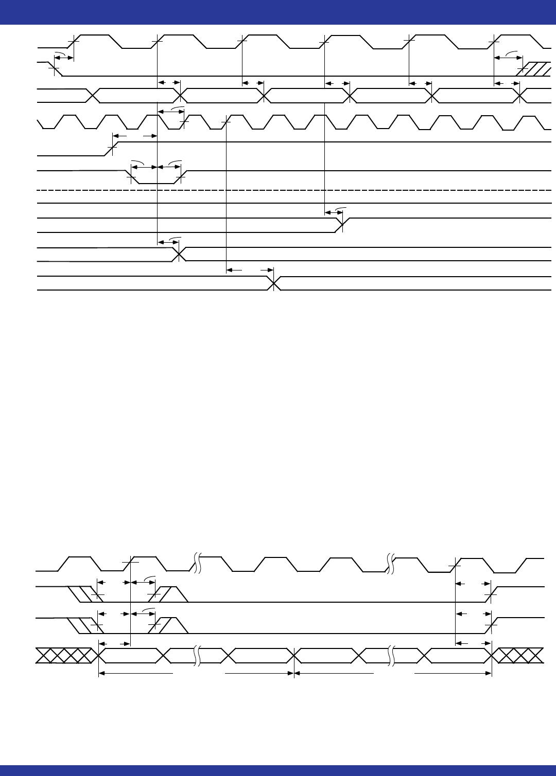
NOTES:
1. If the part is empty at the point of Retransmit, the output ready flag (OR) will be updated based on RCLK (Retransmit clock cycle), valid data will also appear on the output.
2. No more than D - 2 words may be written to the FIFO between Reset (Master or Partial) and Retransmit setup. Therefore, IR will be LOW throughout the Retransmit setup procedure.
D = 1,025 for the IDT72V3640, 2,049 for the IDT72V3650, 4,097 for the IDT72V3660, 8,193 for the IDT72V3670, 16,385 for the IDT72V3680 and 32,769 for the IDT72V3690.
3. OE = LOW.
4. W1, W2, W3 = first, second and third words written to the FIFO after Master Reset.
5. There must be at least two words written to the FIFO before a Retransmit operation can be invoked.
6. RM is set LOW during MRS.
Figure 14. Zero Latency Retransmit Timing (FWFT Mode)
WCLK
SEN
SI
4667 drw20
t
ENH
t
ENS
t
LDS
LD
t
DS
BIT 0
EMPTY OFFSET
BIT X
BIT 0
FULL OFFSET
(1)
t
ENH
BIT X
(1)
t
LDH
t
DH
t
LDH
tRTS
tENH
4667 drw19
tENS
Wx
WCLK
RCLK
REN
RT
OR
PAF
HF
PAE
Q
0
- Q
n
tSKEW2
12
1
tPAFS
tHF
tPAES
Wx+1
2
W3
WEN
tENS
W2
(4)
4
5
tENH
W4
tA
tA
tA
W5
tA
(4)
(4)
3
tA
W1

72V3640L6BB

Mfr. #:
Manufacturer:
IDT
Description:
FIFO 3.3V 32K X 36 SSII
Lifecycle:
New from this manufacturer.
Delivery:
DHL FedEx Ups TNT EMS
Payment:
T/T Paypal Visa MoneyGram Western Union