ADuM2210/ADuM2211 Data Sheet
Rev. F | Page 10 of 17
PIN CONFIGURATIONS AND FUNCTION DESCRIPTIONS
GND
1
1
NC
2
V
DD1
3
V
IA
4
GND
2
16
NC
15
V
DD2
14
V
O
A
13
V
IB
5
V
OB
12
NC
6
NC
1
1
GND
1
7
NC
10
NC
8
GND
2
9
NC = NO CONNECT
NOTES:
1. PIN 1
AND PIN 7 ARE INTERNAL
L
Y CONNECTED,
AND
CONNECTING BOTH
TO GND
1
IS RECOMMENDED.
2. PIN 9 AND PIN 16
ARE INTERNAL
LY
CONNECTED, AND
CONNECTING BOTH T
O GND
2
IS RECOMMENDED.
ADuM2210
TOP VIEW
(Not to Scale)
09233-004
Figure 4. ADuM2210 Pin Configuration
Table 22. ADuM2210 Pin Function Descriptions
Pin No. Mnemonic
Description
1 GND
1
Ground 1. Ground reference for Isolator Side 1.
2 NC No internal connection.
3 V
DD1
Supply Voltage for Isolator Side 1, 3.0 V to 5.5 V.
4
V
IA
Logic Input A.
5 V
IB
Logic Input B.
6 NC No internal connection.
7 GND
1
Ground 1. Ground reference for Isolator Side 1.
8 NC No internal connection.
9
GND
2
Ground 2. Ground reference for Isolator Side 2.
10 NC No internal connection.
11 NC No internal connection.
12 V
OB
Logic Output B.
13 V
OA
Logic Output A.
14 V
DD2
Supply Voltage for Isolator Side 2, 3.0 V to 5.5 V.
15 NC No internal connection.
16 GND
2
Ground 2. Ground reference for Isolator Side 2.
Data Sheet ADuM2210/ADuM2211
Rev. F | Page 11 of 17
GND
1
1
NC
2
V
DD1
3
V
O
A
4
GND
2
16
NC
15
V
DD2
14
V
IA
13
V
IB
5
V
OB
12
NC
6
NC
11
GND
1
7
NC
10
NC
8
GND
2
9
NC = NO CONNECT
NOTES:
1. PIN 1
AND PIN 7
ARE INTERNALLY CONNECTED, AND
CONNECTING BOTH
TO GND
1
IS RECOMMENDED.
2. PIN 9
AND PIN 16 ARE INTERNAL
L
Y CONNECTED, AND
CONNECTING BOTH
TO GND
2
IS RECOMMENDED.
ADuM221
1
TO
P
VIEW
(Not to Scale)
09233-005
Figure 5. ADuM2211 Pin Configuration
Table 23. ADuM2211 Pin Function Descriptions
Pin No. Mnemonic Description
1
GND
1
Ground 1. Ground reference for Isolator Side 1.
2 NC No internal connection.
3 V
DD1
Supply Voltage for Isolator Side 1, 3.0 V to 5.5 V.
4 V
OA
Logic Output A.
5 V
IB
Logic Input B.
6 NC No internal connection.
7 GND
1
Ground 1. Ground reference for Isolator Side 1.
8 NC No internal connection.
9 GND
2
Ground 2. Ground reference for Isolator Side 2.
10 NC No internal connection.
11 NC No internal connection.
12
V
OB
Logic Output B.
13 V
IA
Logic Input A.
14 V
DD2
Supply Voltage for Isolator Side 2, 3.0 V to 5.5 V.
15 NC No internal connection.
16 GND
2
Ground 2. Ground reference for Isolator Side 2.
ADuM2210/ADuM2211 Data Sheet
Rev. F | Page 12 of 17
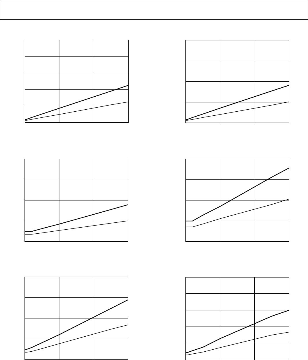
TYPICAL PERFORMANCE CHARACTERISTICS
DATA RATE (Mbps)
CURRENT/CHANNEL (mA)
0
0
6
2
8
10
10 20 30
5V
3V
4
09233-006
Figure 6. Typical Input Supply Current per Channel vs. Data Rate
for 5 V and 3.3 V Operation (No Output Load)
DATA RATE (Mbps)
CURRENT/CHANNEL (mA)
0
0
3
2
1
4
10 20 30
5V
3V
09233-007
Figure 7. Typical Output Supply Current per Channel vs. Data Rate
for 5 V and 3.3 V Operation (No Output Load)
DATA RATE (Mbps)
CURRENT/CHANNEL (mA)
0
0
3
2
1
4
10 20 30
5V
3V
09233-008
Figure 8. Typical Output Supply Current per Channel vs. Data Rate
for 5 V and 3.3 V Operation (15 pF Output Load)
DATA RATE (Mbps)
CURRENT (mA)
0
0
15
10
5
20
10 20 30
5V
3V
09233-009
Figure 9. Typical ADuM2210 V
DD1
Supply Current vs. Data Rate
for 5 V and 3.3 V Operation
DATA RATE (Mbps)
CURRENT (mA)
0
0
3
2
1
4
10 20 30
5V
3V
09233-010
Figure 10. Typical ADuM2210 V
DD2
Supply Current vs. Data Rate
for 5 V and 3.3 V Operation
DATA RATE (Mbps)
CURRENT (mA)
0
0
6
2
8
10
10 20 30
5V
3V
4
09233-011
Figure 11. Typical ADuM2211 V
DD1
or V
DD2
Supply Current vs. Data Rate
for 5 V and 3.3 V Operation

ADUM2210TRWZ

Mfr. #:
Manufacturer:
Analog Devices Inc.
Description:
Digital Isolators Dual-CH Digital 5kV
Lifecycle:
New from this manufacturer.
Delivery:
DHL FedEx Ups TNT EMS
Payment:
T/T Paypal Visa MoneyGram Western Union