Quad-Channel Isolator with
Integrated DC-to-DC Converter
Data Sheet
ADuM5400
Rev. B
Information furnished by Analog Devices is believed to be accurate and reliable. However, no
responsibility is assumed by Analog Devices for its use, nor for any infringements of patents or other
rights of third parties that may result from its use. Specifications subject to change without notice. No
license is granted by implication or otherwise under any patent or patent rights of Analog Devices.
Trademarks and registered trademarks are the property of their respective owners.
One Technology Way, P.O. Box 9106, Norwood, MA 02062-9106, U.S.A.
Tel: 781.329.4700 www.analog.com
Fax: 781.461.3113 ©2008–2012 Analog Devices, Inc. All rights reserved.
FEATURES
isoPower integrated, isolated dc-to-dc converter
Regulated 5 V output
500 mW output power
Quad dc-to-25 Mbps (NRZ) signal isolation channels
Schmitt trigger inputs
16-lead SOIC package with >7.6 mm creepage
High temperature operation: 105°C maximum
High common-mode transient immunity: >25 kV/μs
Safety and regulatory approvals
UL recognition
2500 V rms for 1 minute per UL 1577
CSA Component Acceptance Notice #5A
VDE certificate of conformity (pending)
IEC 60747-5-2 (VDE 0884, Part 2)
V
IORM
= 560 V peak
APPLICATIONS
RS-232/RS-422/RS-485 transceivers
Industrial field bus isolation
Power supply start-up bias and gate drives
Isolated sensor interfaces
Industrial PLCs
GENERAL DESCRIPTION
The ADuM5400
1
device is a quad-channel digital isolator with
isoPower®, an integrated, isolated dc-to-dc converter. Based on
the Analog Devices, Inc., iCoupler® technology, the dc-to-dc
converter provides up to 500 mW of regulated, isolated power
with 5.0 V input and 5.0 V output voltages. This architecture
eliminates the need for a separate, isolated dc-to-dc converter in
low power, isolated designs. The iCoupler chip scale transformer
technology is used to isolate the logic signals and the magnetic
components of the dc-to-dc converter. The result is a small form
factor, total isolation solution.
The ADuM5400 isolator provides four independent isolation
channels in two speed grades (see the Ordering Guide for more
information).
isoPower uses high frequency switching elements to transfer
power through its transformer. Special care must be taken
during printed circuit board (PCB) layout to meet emissions
standards. Refer to the AN-0971 Application Note for details
on board layout recommendations.
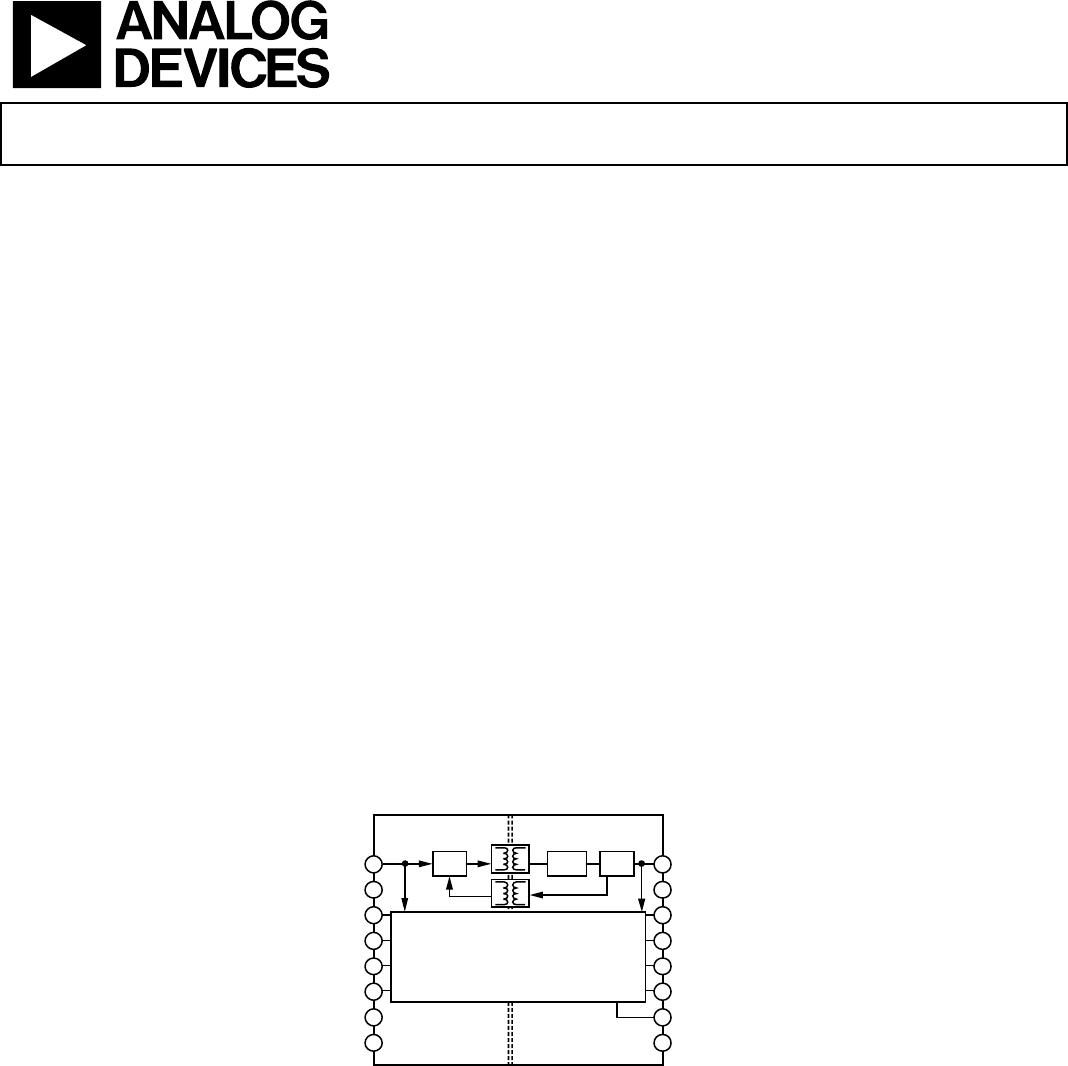
FUNCTIONAL BLOCK DIAGRAM
1
2
3
4
5
6
7
8
16
15
14
13
12
11
10
9
OSC
RECT
4-CHANNEL iCOUPLER CORE
V
DD1
REG
GND
1
V
IA
V
IB
V
IC
V
ID
V
DDL
GND
1
V
ISO
GND
ISO
V
OA
V
OB
V
OC
V
OD
V
ISO
GND
ISO
ADuM5400
07509-001
Figure 1.
1
Protected by U.S. Patents 5,952,849; 6,873,065; 6,903,578; and 7,075,329.
ADUM5400* PRODUCT PAGE QUICK LINKS
Last Content Update: 02/23/2017
COMPARABLE PARTS
View a parametric search of comparable parts.
EVALUATION KITS
EVAL-ADUMQS
DOCUMENTATION
Application Notes
AN-0971: Recommendations for Control of Radiated
Emissions with isoPower Devices
AN-727: iCoupler® Isolation in RS-485 Applications
AN-740: iCoupler® Isolation in RS-232 Applications
AN-770: iCoupler® Isolation in CAN Bus Applications
AN-793: ESD/Latch-Up Considerations with iCoupler®
Isolation Products
AN-825: Power Supply Considerations in iCoupler®
Isolation Products
AN-913: Isolating I2C Interfaces
Data Sheet
ADuM5400: Quad-Channel Isolator with Integrated DC-to-
DC Converter Datasheet
User Guides
UG-042: Evaluating 16-Lead SOIC and 16-Lead QSOP
Digital Isolators
TOOLS AND SIMULATIONS
ADuM5400 IBIS Model (A and C Grades)
REFERENCE DESIGNS
CN0229
REFERENCE MATERIALS
Press
Analog Devices Achieves Major Milestone by Shipping 1
Billionth Channel of iCoupler Digital Isolation
Product Selection Guide
Digital Isolator Product Selection and Resource Guide
Technical Articles
i
Coupler® Products with
iso
Power™ Technology: Signal
and Power Transfer Across Isolation Barrier Using
Microtransformers
High Speed Digital Isolators Using Microscale On-Chip
Transformers
Inside iCoupler® Technology:ADuM347x PWM Controller
and Transformer Driver with Quad-Channel Isolators
Design Summary
Micro-Transformers Provide Signal and Power Isolation for
Hybrid Electric Vehicles
Microtransformer Isolation Benefits Digital Control
N
App
kin Note: Lowering the Power of the ADuM524x
DESIGN RESOURCES
ADUM5400 Material Declaration
PCN-PDN Information
Quality And Reliability
Symbols and Footprints
DISCUSSIONS
View all ADUM5400 EngineerZone Discussions.
SAMPLE AND BUY
Visit the product page to see pricing options.
TECHNICAL SUPPORT
Submit a technical question or find your regional support
number.
DOCUMENT FEEDBACK
Submit feedback for this data sheet.
This page is dynamically generated by Analog Devices, Inc., and inserted into this data sheet. A dynamic change to the content on this page will not
trigger a change to either the revision number or the content of the product data sheet. This dynamic page may be frequently modified.
ADuM5400 Data Sheet
Rev. B | Page 2 of 16
TABLE OF CONTENTS
Features .............................................................................................. 1
Applications ....................................................................................... 1
General Description ......................................................................... 1
Functional Block Diagram .............................................................. 1
Revision History ............................................................................... 2
Specifications ..................................................................................... 3
Electrical Characteristics ............................................................. 3
Package Characteristics ............................................................... 5
Regulatory Information ............................................................... 5
Insulation and Safety Related Specifications ............................ 5
IEC 60747-5-2 (VDE 0884, Part 2):2003-01 Insulation
Characteristics .............................................................................. 6
Recommended Operating Conditions ...................................... 6
Absolute Maximum Ratings ............................................................ 7
ESD Caution .................................................................................. 7
Pin Configuration and Function Descriptions ..............................8
Typical Performance Characteristics ..............................................9
Terminology .................................................................................... 11
Applications Information .............................................................. 12
PCB Layout ................................................................................. 12
EMI Considerations ................................................................... 12
Propagation Delay Parameters ................................................. 13
DC Correctness and Magnetic Field Immunity ..................... 13
Power Consumption .................................................................. 14
Power Considerations ................................................................ 14
Thermal Analysis ....................................................................... 15
Insulation Lifetime ..................................................................... 15
Outline Dimensions ....................................................................... 16
Ordering Guide .......................................................................... 16
REVISION HISTORY
6/12—Rev. A to Rev. B
Created Hyperlink for Safety and Regulatory Approvals
Entry in Features Section ................................................................. 1
Change to EMI Considerations Section ...................................... 12
9/11—Rev. 0 to Rev. A
Changes to Features Section............................................................ 1
Changes to Table 1 ............................................................................ 3
Added Table 2 and Table 3; Renumbered Sequentially ............... 3
Added Table 4 .................................................................................... 4
Changes to Table 5, Table 6, and Table 7 ........................................ 5
Changed DIN V VDE V 0884-10 to IEC 60747-5-2
(VDE 0884, Part 2) Throughout ...................................................... 6
Changes to Table 8 and Table 9 ....................................................... 6
Changes to Table 11 .......................................................................... 7
Added Figure 9; Renumbered Sequentially ................................... 9
Changes to Applications Information Section ........................... 12
Change to Figure 17 ....................................................................... 14
10/08—Revision 0: Initial Version

ADUM5400ARWZ

Mfr. #:
Manufacturer:
Analog Devices / Linear Technology
Description:
Digital Isolators Quad-CH w/ Intg DC/DC Converter
Lifecycle:
New from this manufacturer.
Delivery:
DHL FedEx Ups TNT EMS
Payment:
T/T Paypal Visa MoneyGram Western Union

Products related to this Datasheet