TLE 5206-2
Electrical Characteristics
Data Sheet 15 Rev.1.1, 2007-07-31
Application Modes
1. Simple CW/CCW-Control
For low-cost application simple CW/CCW-Control without any speed regulation is
recommended. A low-speed two-line interface is sufficient for the brake low,
clockwise, counter clockwise and brake high command.
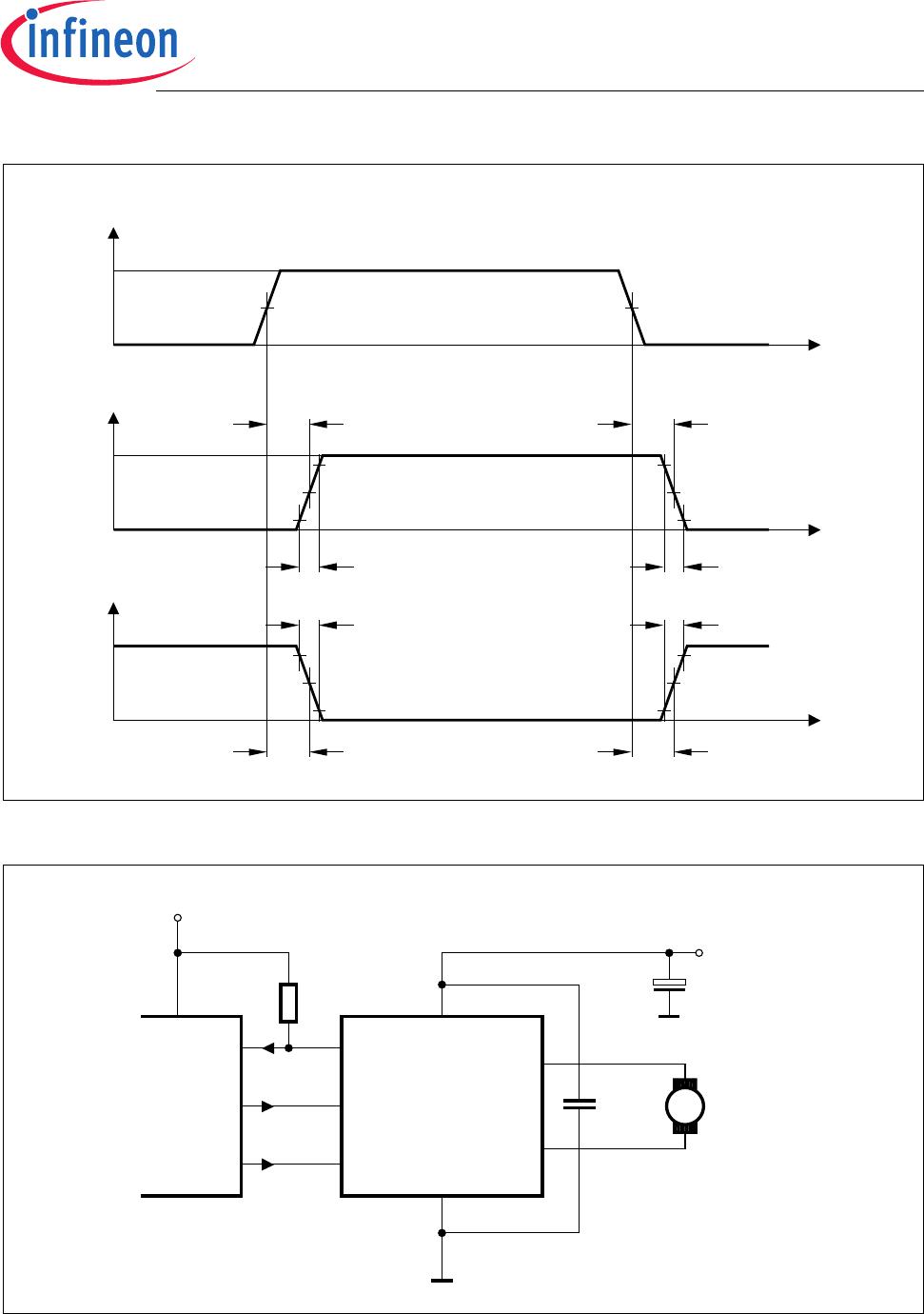
2. Sign/Magnitude Control
For this mode two ports with PWM capability are necessary. Motor turns clockwise
(current flows from OUT1 to OUT2; means: OUT1 is switched HIGH continuously and
OUT2 is PWM controlled.
To achieve motor counter clockwise turning change input signals to:
IN1 = PWM; IN2 = H.
Figure 6 Input/Output Diagram for CW Operation (IN1 = H)
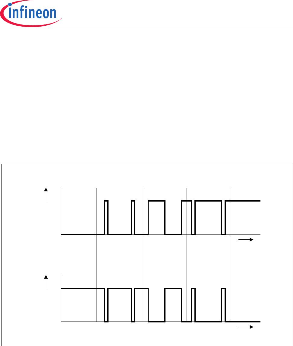
3. Locked Anti-Phase Control
The most important advantage to drive a motor in locked anti-phase mode is: Only one
variable duty cycle signal is necessary in which is encoded both direction- and
amplitude information. So the interface is very simple: A PWM input driven by a
dedicated PWM port from µP.
Fastest High Medium Low Brake to Zero
t
t
Motor
Short
Circuit
IN2
PWM
V
OUT1
- V
OUT2
S
V
0
Motor speed
= 1 = 0.9 = 0.5 = 0.1 = 0
AED02408
νν ν ν ν