TLE 5206-2
Overview
Data Sheet 4 Rev.1.1, 2007-07-31
1.4 Functional Block Diagram
Figure 2 Block Diagram
1
0
0
1
1
1
0
1
0
2
1
0
0
1
1
1
0
1
0
2
IN
OUT
Error Flag
1
7
EF
IN1
IN2
2
3
5
4
6
OUT1
OUT2
GND
V
S
AEB02405
Diagnosis and Protection Circuit 1
Diagnosis and Protection Circuit 2
TLE 5206-2
Overview
Data Sheet 5 Rev.1.1, 2007-07-31
1.5 Circuit Description
Input Circuit
The control inputs consist of TTL/CMOS-compatible schmitt-triggers with hysteresis.
Buffer amplifiers are driven by this stages.
Output Stages
The output stages consist of a DMOS H-bridge. Integrated circuits protect the outputs
against short-circuit to ground and to the supply voltage. Positive and negative voltage
spikes, which occur when switching inductive loads, are limited by integrated
freewheeling diodes.
A monitoring circuit for each output transistor detects whether the particular transitor is
active and in this case prevents the corresponding source transistor (sink transistor) from
conducting in sink operation (source operation). Therefore no crossover currents can
occur.
1.6 Input Logic Truth Table
Functional Truth Table
IN1 IN2 OUT1 OUT2 Comments
L L L L Brake; both low side transistors turned-ON
L H L H Motor turns counterclockwise
H L H L Motor turns clockwise
H H H H Brake; both high side transistors turned-ON
Notes for Output Stage
Symbol Value
L Low side transistor is turned-ON
High side transistor is turned-OFF
H High side transistor is turned-ON
Low side transistor is turned-OFF
TLE 5206-2
Overview
Data Sheet 6 Rev.1.1, 2007-07-31
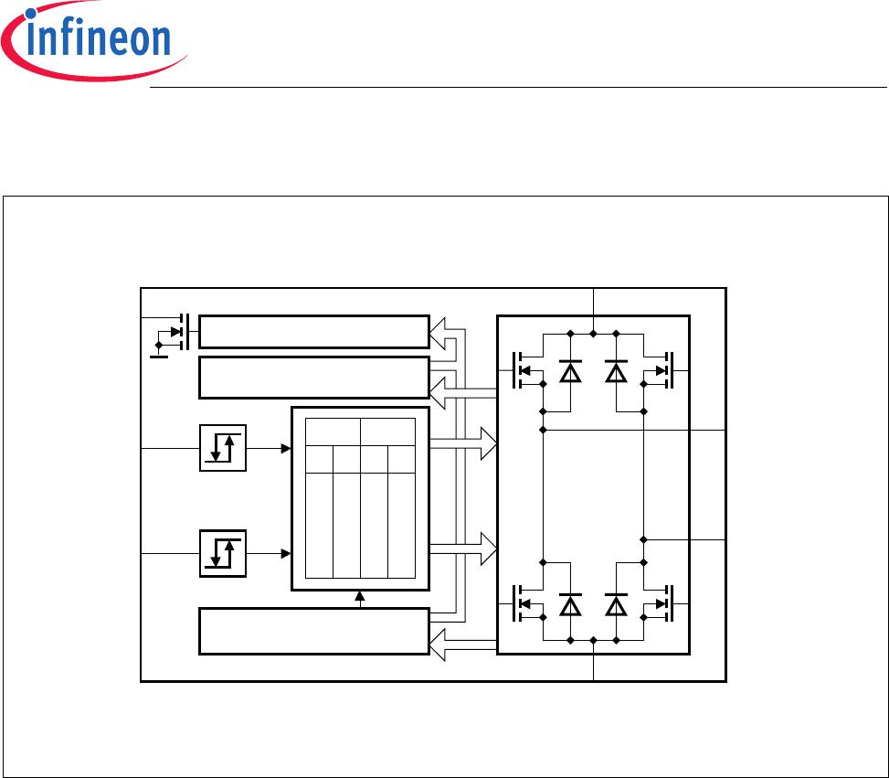
1.7 Monitoring Functions
Undervoltage lockout (UVLO):
When
V
S
reaches the switch on voltage V
SON
the IC becomes active with a hysteresis.
All output transistors are switched off if the supply voltage
V
S
drops below the switch off
value
V
SOFF.
1.8 Protective Function
Various errors like short-circuit to +
V
S
, ground or across the load are detected. All faults
result in turn-OFF of the output stages after a delay of 50 µs and setting of the error flag
EF to ground. Changing the inputs resets the error flag.
a. Output Shorted to Ground Detection
If a high side transistor is switched on and its output is shorted to ground, the output
current is internally limited. After a delay of 50 µs all outputs will be switched-OFF and
the error flag is set.
b. Output Shorted to +
V
S
Detection
If a low side transistor is switched on and its output is shorted to the supply voltage,
the output current is internally limited. After a delay of 50 µs all outputs will be
switched-OFF and the error flag is set.
c. Overload Detection
An internal circuit detects if the current through the low side transistor exceeds the
trippoint
I
SDL
. In this case all outputs are turned off after 50 µs and the error flag is set.
d. Overtemperature Protection
At a junction temperature higher than 150 °C the thermal shutdown turns-OFF, all four
output stages commonly and the error flag is set with a delay.

TLE52062SAKSA1

Mfr. #:
Manufacturer:
Infineon Technologies
Description:
Motor / Motion / Ignition Controllers & Drivers POWERTRAIN
Lifecycle:
New from this manufacturer.
Delivery:
DHL FedEx Ups TNT EMS
Payment:
T/T Paypal Visa MoneyGram Western Union

Products related to this Datasheet