©2011 Silicon Storage Technology, Inc. DS25080A 11/11
22
2 Mbit SPI Serial Flash
SST25LF020A
Not Recommended for New Designs
A
Microchip Technology Company
Figure 19: Hold Timing Diagram
Figure 20: Power-up Timing Diagram
T
HZ
T
LZ
T
HHH
T
HLS
T
HLH
T
HHS
1242 F18.0
HOLD#
CE#
SCK
SO
SI
Time
V
DD
Min
V
DD
Max
V
DD
Device fully accessible
T
PU-READ
T
PU-WRITE
Chip selection is not allowed.
All commands are rejected by the device.
1242 F19.0
©2011 Silicon Storage Technology, Inc. DS25080A 11/11
23
2 Mbit SPI Serial Flash
SST25LF020A
Not Recommended for New Designs
A
Microchip Technology Company
Figure 21: AC Input/Output Reference Waveforms
Figure 22: A Test Load Example
1242 F20.0
REFERENCE POINTS OUTPUTINPUT
V
HT
V
LT
V
HT
V
LT
V
IHT
V
ILT
AC test inputs are driven at V
IHT
(0.9V
DD
) for a logic “1” and V
ILT
(0.1V
DD
) for a logic “0”. Mea-
surement reference points for inputs and outputs are V
HT
(0.7V
DD
) and V
LT
(0.3V
DD
). Input rise
and fall times (10% 90%) are <5 ns.
Note: V
HT
-V
HIGH
Test
V
LT
-V
LOW
Test
V
IHT
-V
INPUT
HIGH Test
V
ILT
-V
INPUT
LOW Test
1242 F21.0
TO TESTER
TO DUT
C
L
©2011 Silicon Storage Technology, Inc. DS25080A 11/11
24
2 Mbit SPI Serial Flash
SST25LF020A
Not Recommended for New Designs
A
Microchip Technology Company
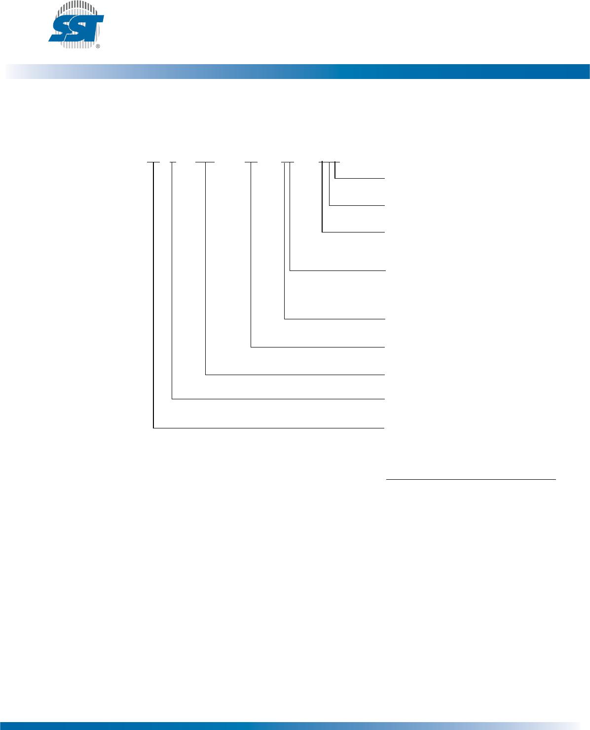
Product Ordering Information
Valid combinations for SST25LF020A
SST25LF020A-33-4C-SAE SST25LF020A-33-4C-QAE
SST25LF020A-33-4I-SAE SST25LF020A-33-4I-QAE
SST25LF020A-33-4E-SAE SST25LF020A-33-4E-QAE
Note:Valid combinations are those products in mass production or will be in mass production. Consult your SST
sales representative to confirm availability of valid combinations and to determine availability of new combi-
nations.
SST 25 LF 020A - 33 - 4I - QAE
XX XX XXXX - XX - XX
-
XXX
Environmental Attribute
E
1
= non-Pb
Package Modifier
A = 8 leads or contacts
Package Type
S = SOIC 150 mil body width
Q = WSON
Operation Temperature
C = Commercial = 0°C to +70°C
I = Industrial = -40°C to +85°C
E = Extended = -20°C to +85°C
Minimum Endurance
4 = 10,000 cycles
Operating Frequency
33 = 33 MHz
Device Density
020 = 2 Mbit
Voltage
L = 3.0-3.6V
Product Series
25 = Serial Peripheral Interface
flash memory
1. Environmental suffix “E” denotes non-Pb sol-
der.
SST non-Pb solder devices are “RoHS Com-
pliant”.

SST25LF020A-33-4I-QAE

Mfr. #:
Manufacturer:
Microchip Technology
Description:
NOR Flash 2Mbit 33MHz
Lifecycle:
New from this manufacturer.
Delivery:
DHL FedEx Ups TNT EMS
Payment:
T/T Paypal Visa MoneyGram Western Union