September 2009 Doc ID 3080 Rev 6 1/10
10
SM15T
Transil™
Features
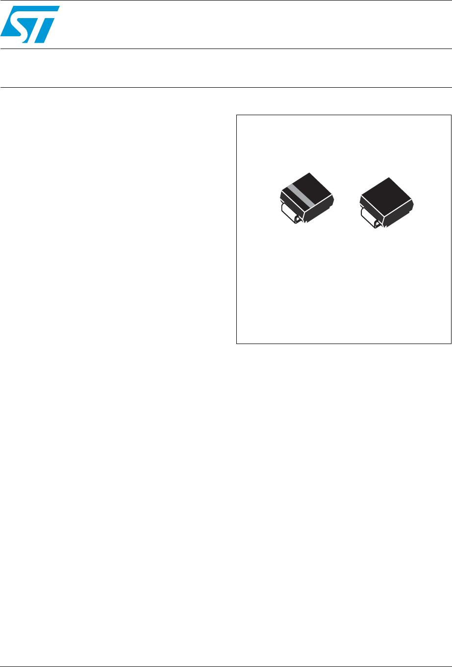
■ Peak pulse power:
– 1500 W (10/1000 µs)
– 10 kW (8/20 µs)
■ Breakdown voltage range: from 6.8 V to 220 V
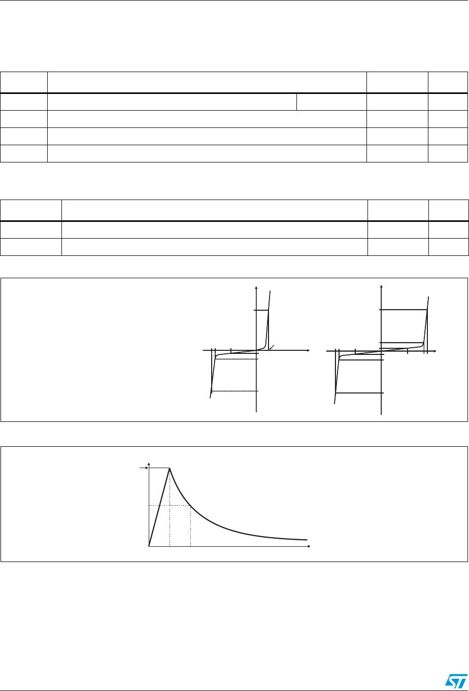
■ Unidirectional and bidirectional types
■ Low leakage current:
– 0.2 µA at 25 °C
– 1 µA at 85 °C
■ Operating T
j max
: 150 °C
■ High power capability at T
jmax
:
– 1250 W (10/1000 µs)
■ JEDEC registered package outline
Complies with the following standards
■ IEC 61000-4-2 level 4
– 15 kV (air discharge)
– 8 kV (contact discharge)
■ IEC 61000-4-5
– See Tabl e 3 for surge level
■ MIL STD 883G, method 3015-7: class 3B
– 25 kV HBM (human body model)
■ UL 497B file number: QVGQ2.E136224
■ Resin meets UL 94, V0
■ MIL-STD-750, method 2026 soldererabilty
■ EIA STD RS-481 and IEC 60286-3 packing
■ IPC 7531 footprint
Description
The SM15T Transil series has been designed to
protect sensitive equipment against electrostatic
discharges according to IEC 61000-4-2, and
MIL STD 883, method 3015, and electrical over
stress according to IEC 61000-4-4 and 5. These
devices are more generally used against surges
below 1500 W (10/1000 µs).
Planar technology makes these devices suitable
for high-end equipment and SMPS where low
leakage current and high junction temperature are
required to provide reliability and stability over
time.
SM15T are packaged in SMC (SMC footprint in
accordance with IPC 7531 standard).
TM: Transil is a trademark of STMicroelectronics
K
A
Unidirectional Bidirectional
SMC
(JEDEC DO-214AB)
www.st.com