Electrical Specifications
Stresses greater than those listed may cause permanent damage to the module. This is a
stress rating only, and functional operation of the module at these or any other condi-
tions outside those indicated in each device's data sheet is not implied. Exposure to ab-
solute maximum rating conditions for extended periods may adversely affect reliability.
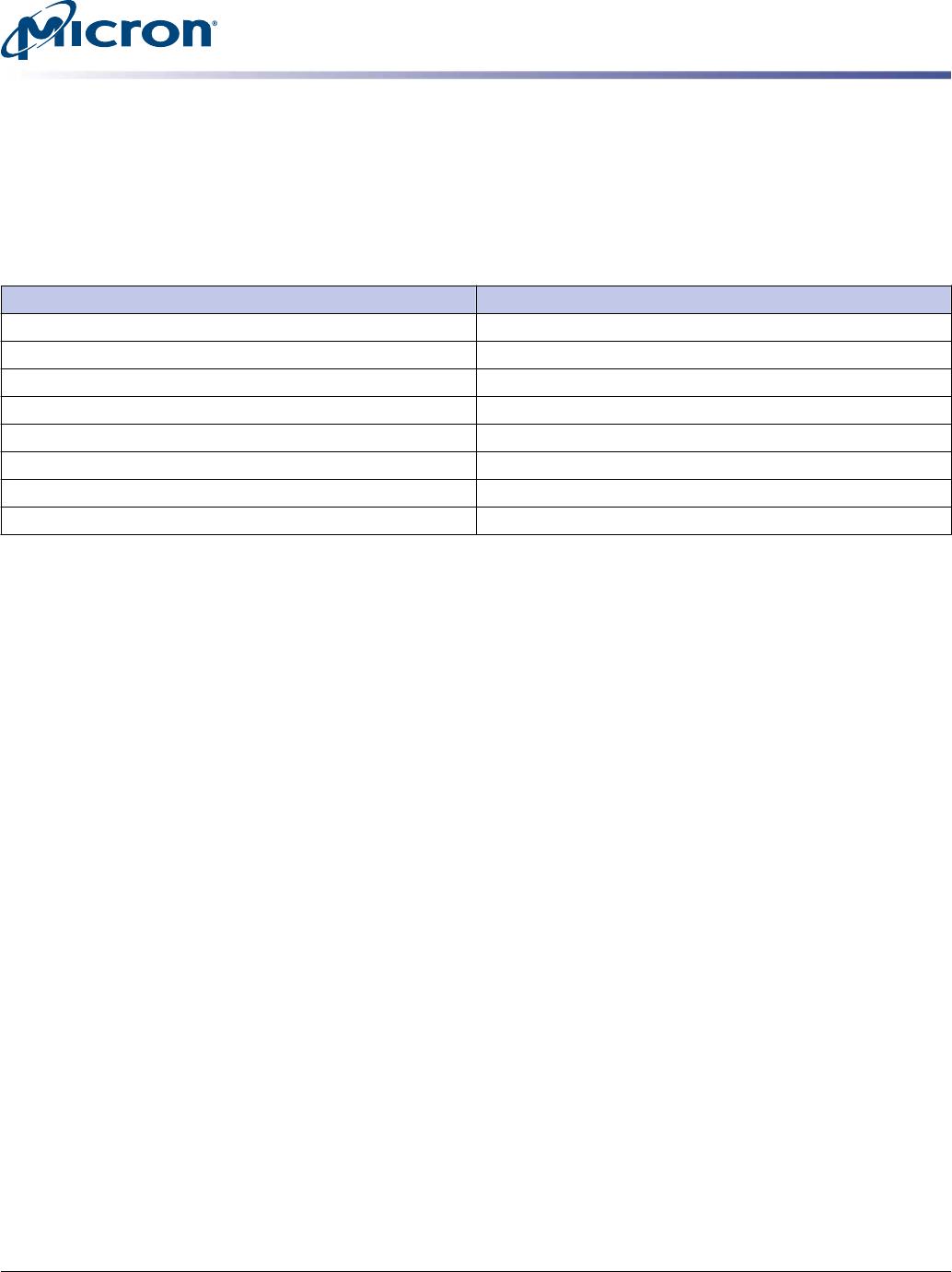
Table 9: Absolute Maximum Ratings
Symbol Parameter Min Max Units
V
DD
V
DD
supply voltage relative to V
SS
–0.4 1.975 V
V
IN
, V
OUT
Voltage on any pin relative to V
SS
–0.4 1.975 V
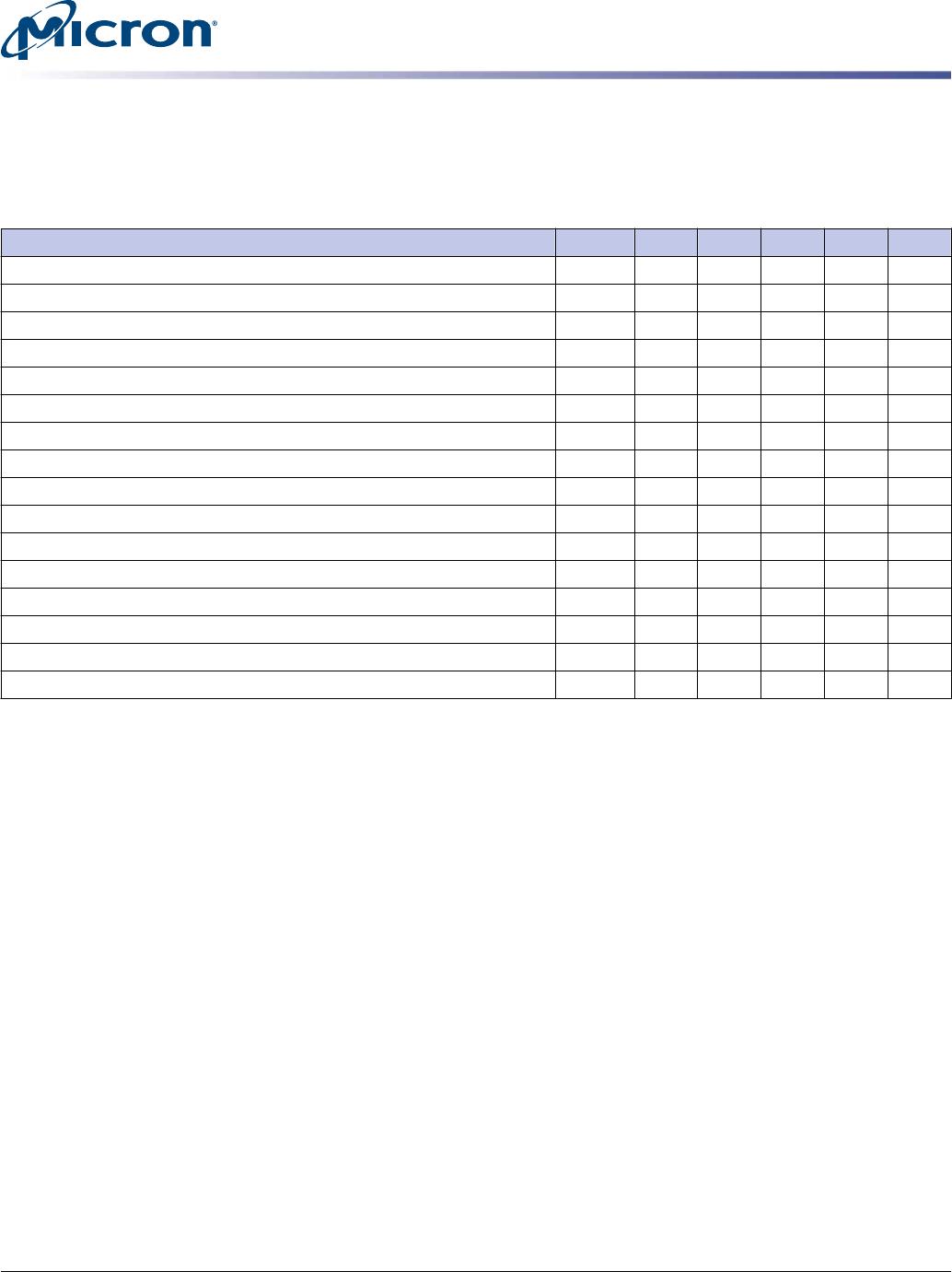
Table 10: Operating Conditions
Symbol Parameter Min Nom Max Units Notes
V
DD
V
DD
supply voltage 1.425 1.5 1.575 V
I
VTT
Termination reference current from V
TT
–600 – 600 mA
V
TT
Termination reference voltage – command address
bus
0.483 x V
DD
0.5 x V
DD
0.517 x V
DD
V 1
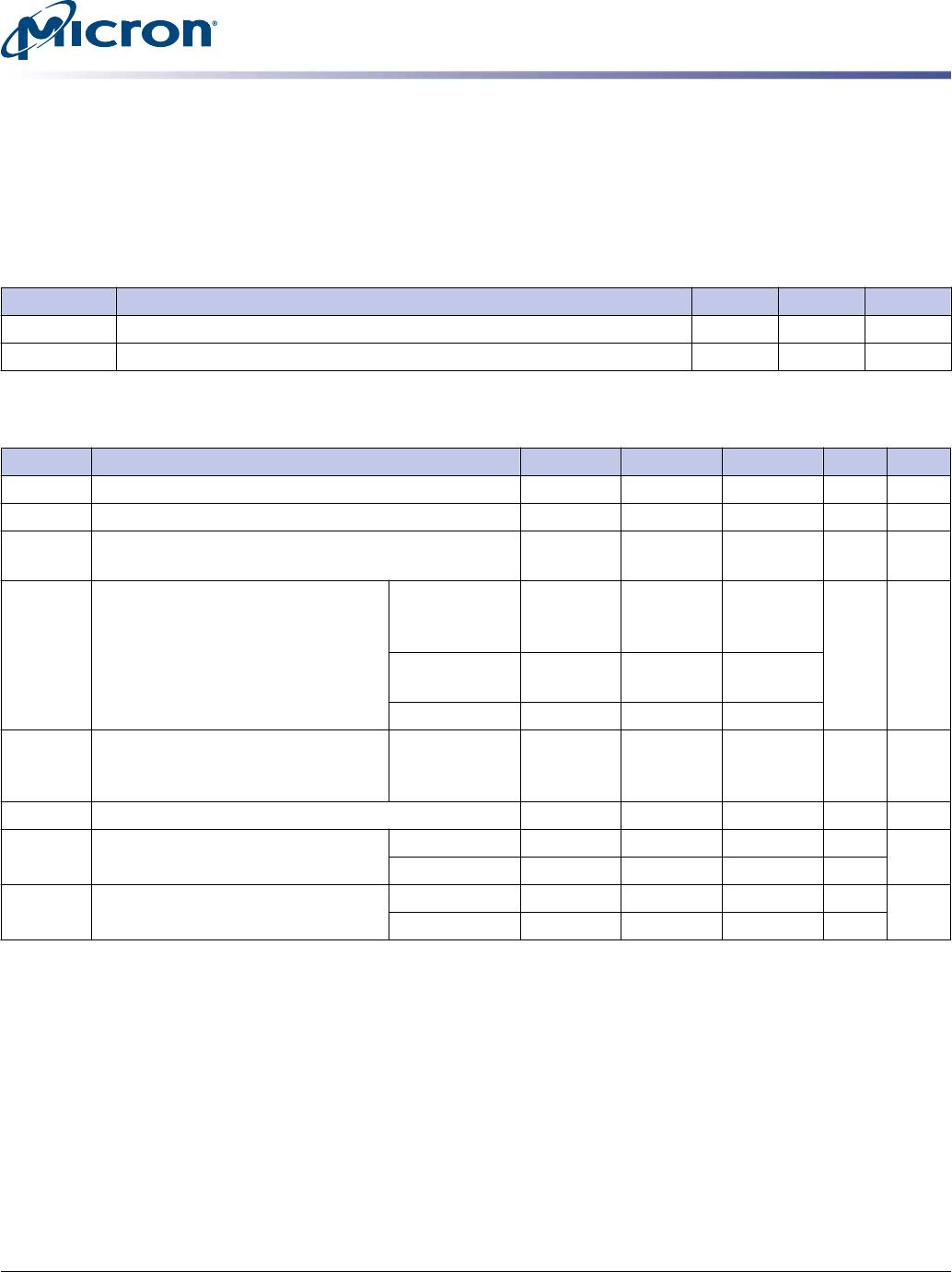
I
I
Input leakage current;
Any input 0V ≤ V
IN
≤ V
DD
;
V
REF
input 0V ≤ V
IN
≤ 0.95V
(All other pins not under test = 0V)
Address inputs
RAS#, CAS#,
WE#, BA
–32 0 32 µA
S#, CKE, ODT,
CK, CK#
–16 0 16
DM –4 0 4
I
OZ
Output leakage current;
0V ≤ V
OUT
≤ V
DDQ
; DQs and ODT are
disabled
DQ, DQS, DQS# –10 0 10 µA
I
VREF
V
REF
leakage current; V
REF
= valid V
REF
level –16 0 16 µA
T
A
Module ambient operating tempera-
ture
Commercial 0 – 70 °C 2, 3
Industrial –40 – 85 °C
T
C
DDR3 SDRAM component case oper-
ating temperature
Commercial 0 – 95 °C 2, 3, 4
Industrial –40 – 95 °C
Notes:
1. V
TT
termination voltage in excess of the stated limit will adversely affect the command
and address signals’ voltage margin and will reduce timing margins.
2. T
A
and T
C
are simultaneous requirements.
3. For further information, refer to technical note TN-00-08: ”Thermal Applications,”
available on Micron’s Web site.
4. The refresh rate is required to double when 85°C < T
C
≤ 95°C.
2GB, 4GB, 8GB (x64, DR) 240-Pin DDR3 UDIMM
Electrical Specifications
PDF: 09005aef837cdd2d
jtf16c256_512_1gx64az.pdf - Rev. I 04/13 EN
10
Micron Technology, Inc. reserves the right to change products or specifications without notice.
© 2008 Micron Technology, Inc. All rights reserved.