VS-ST103S08PFL1

VS-ST103SP Series
www.vishay.com
Vishay Semiconductors
Revision: 11-Mar-14
7
Document Number: 94365
For technical questions within your region: DiodesAmericas@vishay.com
, DiodesAsia@vishay.com, DiodesEurope@vishay.com
THIS DOCUMENT IS SUBJECT TO CHANGE WITHOUT NOTICE. THE PRODUCTS DESCRIBED HEREIN AND THIS DOCUMENT
ARE SUBJECT TO SPECIFIC DISCLAIMERS, SET FORTH AT www.vishay.com/doc?91000
Fig. 14 - Maximum On-State Energy Power Loss Characteristics
Fig. 15 - Gate Characteristics
Pulse Basewidth (µs)
Peak On-State Current (A)
10 100 1000 10 000
10
100
1000
10 000
t
p
ST103S Series
Sinusoidal pulse
100 000
0.1
0.2
0.5
2
3
1
5
10
20 joules per pulse
Pulse Basewidth (µs)
Peak On-State Current (A)
10 100 1000 10 000
10
100
1000
10 000
100 000
0.1
0.2
0.5
2
3
1
5
10
20 joules per pulse
t
p
ST103S Series
Rectangular pulse
dI/dt = 50 A/µs
0.1
1
10
100
0.001
Instantaneous Gate Current (A)
Instantaneous Gate Voltage (V)
0.01 0.1 1 10 100
V
GD
I
GD
(1) (2) (3)
Device: ST103S Series
(4)
Frequency limited by P
G(AV)
T
J
= 25 °C
T
J
= 40 °C
T
J
= 125 °C
(a)
(b)
Rectangular gate pulse
a) Recommended load line for
rated di/dt: 20 V, 10 Ω; t
r
1 µs
b) Recommended load line for
30 % rated di/dt: 10 V, 10 Ω
t
r
1 µs
(1) P
GM
= 10 W, t
p
= 20 ms
(2) P
GM
= 20 W, t
p
= 10 ms
(3) P
GM
= 40 W, t
p
= 5 ms
(4) P
GM
= 60 W, t
p
= 3.3 ms
VS-ST103SP Series
www.vishay.com
Vishay Semiconductors
Revision: 11-Mar-14
8
Document Number: 94365
For technical questions within your region: DiodesAmericas@vishay.com
, DiodesAsia@vishay.com, DiodesEurope@vishay.com
THIS DOCUMENT IS SUBJECT TO CHANGE WITHOUT NOTICE. THE PRODUCTS DESCRIBED HEREIN AND THIS DOCUMENT
ARE SUBJECT TO SPECIFIC DISCLAIMERS, SET FORTH AT www.vishay.com/doc?91000
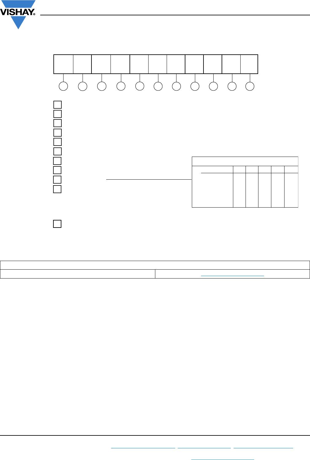
ORDERING INFORMATION TABLE
LINKS TO RELATED DOCUMENTS
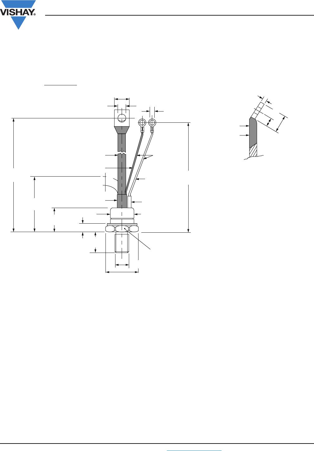
Dimensions www.vishay.com/doc?95003
- Thyristor
2
- Essential part number
3
- 3 = Fast turn-off
4
- S = Compression bonding stud
5
- Voltage code x 100 = V
RRM
(see Voltage ratings table)
6
- P = Stud base 1/2"-20UNF-2A
7
- Reapplied dV/dt code (for t
q
test conditions)
8
-t
q
code9
- 0 = Eyelet terminals
(gate and aux. cathode leads)
1 = Fast-on terminals
(gate and aux. cathode leads)
dV/dt - t
q
combinations available
dV/dt (V/µs) 20 50 100 200 400
10
12
15
18
20
25
CN
CM
CL
CP
CK
DN
DM
DL
DP
DK
FL*
FM
FN*
EK
EP
EL
EM
EN
HP
HL
HM
FK
FP
HJ
HK
-
----
t
q
(µs)
* Standard part number.
All other types available only on request.
Device code
51 32 4 6 7 8 9 10 11
ST 10 3 S 08 P F N 0 P
11
10
VS-
1 - Vishay Semiconductors product
- None = Standard production
- P = Lead (Pb)-free
Document Number: 95003 For technical questions, contact: indmodules@vishay.com
www.vishay.com
Revision: 30-Sep-08 1
TO-209AC (TO-94) for ST083S and ST103S Series
Outline Dimensions
Vishay Semiconductors
DIMENSIONS in millimeters (inches)
Ceramic housing
1/2"-20UNF-2A
SW 27
Red shrink
Red cathode
Red silicon rubber
12.5 (0.49) MAX.
29 (1.14)
MAX.
21 (0.83)
MAX.
157 (6.18)
170 (6.69)
70 (2.75)
MIN.
Ø 4.3 (0.17)
Ø 8.5 (0.33)
16.5 (0.65) MAX.
29.5 (1.16) MAX.
C.S. 0.4 mm
2
White shrink
(0.0006 s.i.)
Ø 22.5 (0.88) MAX.
White gate
215 ± 10
(8.46 ± 0.39)
C.S. 16 mm
2
(0.025 s.i.)
Flexible lead
2.6 (0.10) MAX.
9.5 (0.37) MIN.
20 (0.79) MIN.

VS-ST103S08PFL1

Mfr. #:
Manufacturer:
Vishay Semiconductors
Description:
SCRs Thyristors - TO-83/94 COM RD-e3
Lifecycle:
New from this manufacturer.
Delivery:
DHL FedEx Ups TNT EMS
Payment:
T/T Paypal Visa MoneyGram Western Union