MP8042 –24V, 5A DUAL CHANNEL POWER HALF-BRIDGE
MP8042 Rev. 0.91 www.MonolithicPower.com 7
5/5/2010 MPS Proprietary Information. Unauthorized Photocopy and Duplication Prohibited.
© 2010 MPS. All Rights Reserved.
OPERATION
The MP8042 is a high voltage, dual channel
power half- bridge that can be configured as the
output of a Class D amplifier. The output is in
phase with the input, and the dead time is
optimized for symmetrical performance,
regardless of load conditions.
When shutdown pin (
SHDN ) is low, both
channels 1 and 2 will be shut off. When the
standby pin (
STBY ) is pulled low, it causes the
outputs of both channels to go into high
impedance. However, when the voltage across
the BST1/2 and OUT1/2 pins drops sufficiently
low, the bottom MOSFET is turned on to refresh
the external bootstrap capacitor. For a
bootstrap capacitor of 100nF, the refresh time is
approximately 300ns.
In order to prevent erratic operation, two under
voltage lockout (UVLO) circuits are used. One
of them is to ensure that the supply for the
bottom gate drive circuit is sufficiently high and
the other is for the top gate driver.
Fault Protection
To protect the power MOSFETs, two layers of
protection are provided. The first is the current
limit, wherein if the current through either the
top or the bottom MOSFET exceeds an
internally preset value of 5A, that particular
MOSFET is immediately shut down and the
complementary MOSFET is turned on. If this
fails to reset the current and there is an
indication that the current is going to runaway,
the current foldback will kick in. This ensures
that the current is reset close to zero before
resuming operation.
Thermal monitoring is also integrated into the
MP8042. If the die temperature rises above
150°C, both switches are turned off. The
temperature must fall below 130°C before
normal operation resumes.
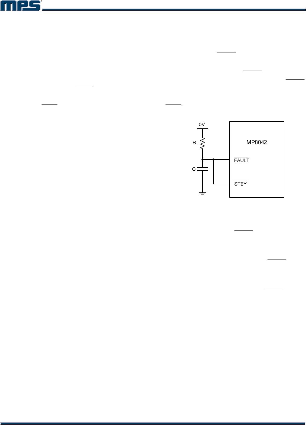
To enhance the robustness of the device under
short circuit condition, a capacitor can be
connected to the
FAULT
pin, as shown in figure
1. The time constant of the RC is selected to be
greater than 50ms for the
FAULT node to reach
1V. Under short circuit condition, the
FAULT
node will be reset to zero and the part will be
place in standby mode until the voltage at the
STBY pin is above 1V.
Figure 1— Fault Protection Circuit
Fault Output
The MP8042 includes an open drain, active low
fault indicator output (
FAULT ). A fault will be
indicated if the current limit is tripped or the
thermal shutdown is tripped.
A fault on any channel causes the
FAULT pin to
be pulled low. However, only that fault channel
has its output set to high impedance.
Do not apply more than 6V to the
FAULT pin.