10
COMMERCIAL TEMPERATURE RANGE
IDT72420/72200/72210/72220/72230/72240 CMOS SYNCFIFO™
64 x 8, 256 x 8, 512 x 8, 1,024 x 8, 2,048 x 8, 4,096 x 8
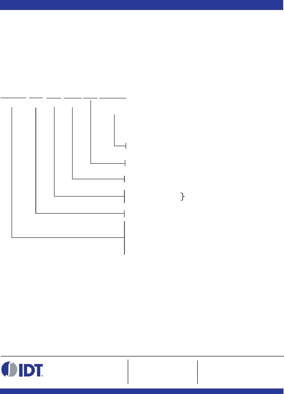
Figure 10. Block Diagram of Single 64 x 8, 256 x 8, 512 x 8, 1,024 x 8, 2,048 x 8, 4,096 x 8 Synchronous FIFO
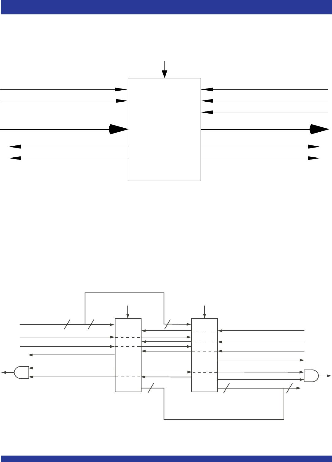
WIDTH EXPANSION CONFIGURATION - Word width may be increased
simply by connecting the corresponding input control signals of multiple
devices. A composite flag should be created for each of the endpoint status
flags (EF and FF) The partial status flags (AE and AF) can be detected from
any one device. Figure 11 demonstrates a 16-bit word width by using two
IDT72420/72200/72210/72220/72230/72240s. Any word width can be
attained by adding additional IDT72420/72200/72210/72220/72230/72240s.
Figure 11. Block Diagram of 64 x 16, 256 x 16, 512 x 16, 1,024 x 16, 2,048 x 16, 4,096 x 16
Synchronous FIFO Used in a Width Expansion Configuration
WRITE CLOCK (WCLK) READ CLOCK (RCLK)
READ ENABLE (REN)
OUTPUT ENABLE (OE)
FULL FLAG (FF)
ALMOST-FULL (AF)
EMPTY FLAG (EF)
ALMOST-EMPTY(AE)
IDT
72420
72200
72210
72220
72230
72240
RESET (RS)
WRITE ENABLE (WEN)
DATA IN (D
0-D7) DATA OUT (Q0-Q7)
2680 drw 12
DATA IN (D)
WRITE CLOCK (WCLK)
16 8 8
RESET (RS)
READ CLOCK (RCLK)
DATA OUT (Q)
8
16
WRITE ENABLE (WEN)
FULL FLAG (FF) #1
ALMOST-EMPTY (AE)
EMPTY FLAG (EF) #2
OUTPUT ENABLE (OE)
READ ENABLE (REN)
8
IDT
72420
72200
72210
72220
72230
72240
FULL FLAG (FF) #2
EMPTY FLAG (EF) #1
RESET (RS)
IDT
72420
72200
72210
72220
72230
72240
2680 drw13
ALMOST-FULL (AF)
OPERATING CONFIGURATIONS
SINGLE DEVICE CONFIGURATION - A single IDT72420/72200/72210/
72220/72230/72240 may be used when the application requirements are
for 64/256/512/1,024/2,048/4,096 words or less. See Figure 10.