LTC4245
4
4245fa
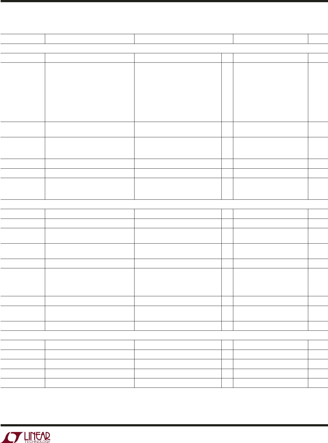
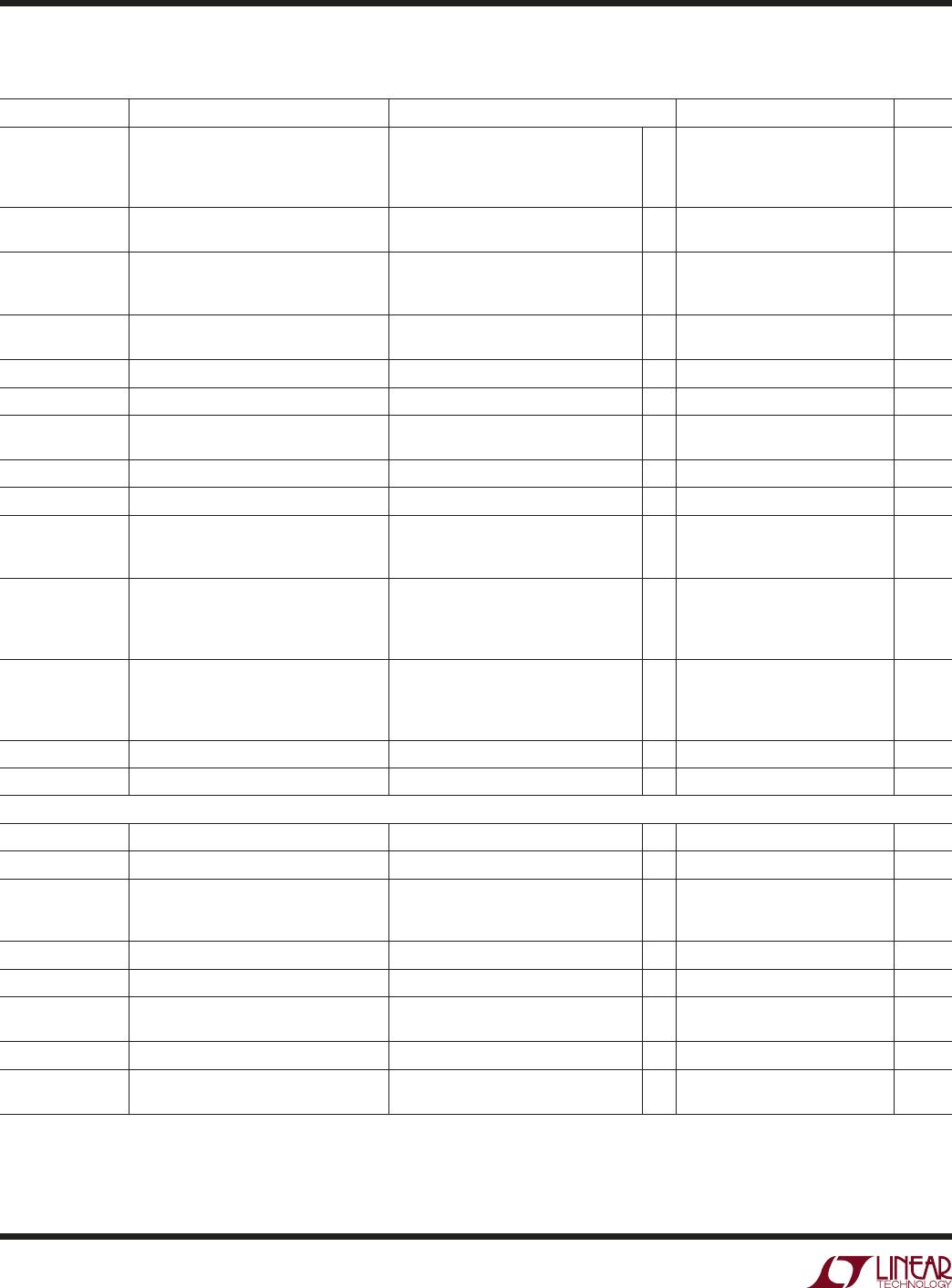
SYMBOL PARAMETER CONDITIONS MIN TYP MAX UNITS
V
PB(TH)
Power Bad Threshold Voltage 12V
OUT
5V
OUT
, V
CFG
= 0V, Open
5V
OUT
When V
CFG
= V
CC
, 3V
OUT
V
EEOUT
, V
CFG
= 0V
●
●
●
●
10.8
4.5
2.8
–10.8
11.1
4.63
2.9
–11.1
11.4
4.75
3.0
–11.4
V
V
V
V
V
IN(TH)
Logic Input Threshold PGI, PCI_RST#, GPIOn
SDA, SCL
●
●
0.8
1.6
1.0
1.8
1.2
2.0
V
V
I
IN
Pin Input Current ON, PGI, PCI_RST#, V = 1.2V
SDA, SCL, ALERT#, GPIOn, HEALTHY#,
LOCAL_PCI_RST#, V = 6V
●
0±1 μA
V
OL
Output Low Voltage SDA, ALERT#, I = 5mA; GPIOn,
HEALTHY#, LOCAL_PCI_RST#, I = 3mA
●
0.2 0.4 V
V
TRI(H)
ADR2, ADR3, CFG Input High Threshold
●
V
CC
–0.8 V
CC
–0.4 V
CC
–0.2 V
V
TRI(L)
ADRn, CFG Input Low Threshold
●
0.2 0.4 0.8 V
I
TRI(IN,HL)
ADR2, ADR3, CFG High, Low Input
Current
V = 0V, V
CC
●
±80 μA
I
TRI(IN,Z)
ADR2, ADR3, CFG High Z Input Current V = 0.8V, V
CC
–0.8V
●
±10 μA
I
ADR01(IN)
ADR0, ADR1 Input Current V
ADR0
, V
ADR1
= 0V, V
CC
●
–30 1 μA
I
SENSE
Sense Pin Input Current
12V
SENSE
, 5V
SENSE
, 3V
SENSE
V
EESENSE
After Start-Up
V
SENSE
= V
IN
V
VEESENSE
= –12V
●
●
0.3
–30
1
–45
μA
μA
I
OUT(ON)
OUT Pin Input Current V
12VOUT
= 12V, V
ON
= 2V
V
5VOUT
= 5V, V
ON
= 2V
V
3VOUT
= 3.3V, V
ON
= 2V
V
VEEOUT
= –12V, V
ON
= 2V
●
●
●
●
200
275
75
–200
280
390
105
–280
μA
μA
μA
μA
R
OUT(DIS)
OUT Pin Discharge Resistance V
12VOUT
= 6V, V
ON
= 0V
V
5VOUT
= 3V, V
ON
= 0V
V
3VOUT
= 2V, V
ON
= 0V
V
VEEOUT
= –6V, V
ON
= 0V
●
●
●
●
650
125
130
1300
1000
180
190
1800
1800
325
340
3200
Ω
Ω
Ω
Ω
I
VEEOUT(UP)
V
EEOUT
Pull-Up Current V
VEEOUT
= 0V
●
–36 –54 μA
V
PXG
PRECHARGE Voltage I
PRECHARGE
= Open, –70mA (Note 6)
●
0.95 1 1.05 V
Timer, Soft-Start
V
TIMER(H)
TIMER Pin High Threshold V
TIMER
Rising
●
2.5 2.56 2.62 V
V
TIMER(L)
TIMER Pin Low Threshold V
TIMER
Falling
●
0.1 0.23 0.4 V
I
TIMER
TIMER Pin Pull-Up Current During Start-Up, V
TIMER
= 0V
During PGI Timeout, V
TIMER
= 0V
During Auto-Retry, V
TIMER
= 0V
●
●
●
–80
–8
–1.5
–100
–10
–2
–120
–12
–2.5
μA
μA
μA
K
TMRATIO
TIMER Pin Current Ratio (I
TIMER(RTRY)
/I
TIMER(START)
)
●
1.6 2 2.7 %
K
TMCAP
Start-Up Time per TIMER Capacitance ((V
TIMER(H)
– V
TIMER(L)
)/I
TIMER(START)
)
●
20 23.3 26 ms/μF
I
SS
SS Pin Pull-Up Current Fast Ramp, V
SS
= 0V
Slow Ramp, V
SS
= 2V
●
●
–16
–1.5
–20
–2
–24
–2.5
μA
μA
R
TS(DIS)
TIMER, SS Discharge Resistance V
TIMER
= 1.2V, V
SS
= 1.2V
●
225 400
Ω
G
SS
Gain from SS Pin to Foldback Current
Limit (ΔV
SNS(FB)
/ΔV
SS
)
12V
IN
, V
EEIN
5V
IN
, 3V
IN
46
23
mV/V
mV/V
The ● denotes the specifi cations which apply over the full operating temperature
range, otherwise specifi cations are at T
A
= 25°C. V
12VIN
= 12V, V
5VIN
= 5V, V
3VIN
= 3.3V, V
VEEIN
= –12V, unless otherwise noted.
ELECTRICAL CHARACTERISTICS