TC652/TC653
DS21452C-page 4 2002-2012 Microchip Technology Inc.
2.0 PIN DESCRIPTIONS
The descriptions of the pins are listed in Table 2-1.
TABLE 2-1: PIN FUNCTION TABLE
Pin No.
(8-Pin MSOP)
Symbol Description
1V
DD
Power Supply Input. May be independent of fan power supply.
2FAULT
Fan Fault Alert, Active-Low Output. FAULT goes low to indicate a fan FAULT condition.
When FAULT occurs, the device is latched in Shutdown mode with PWM low. Toggling
the SHDN
pin or cycling the V
DD
will release the part and fan from shutdown. FAULT will
unconditionally remain high during shutdown.
3 SHDN
Fan Shutdown, Active-Low Input. During Shutdown mode the chip still monitors
temperature and T
OVER
is low if temperature rises above factory set point.
4 GND Ground return for all TC652/TC653 functions.
5 SENSE Detect Fan Pulses Input. Pulses are detected at this pin as fan rotation chops the current
through the sense resistor, R
SENSE
. The absence of pulses indicates a Fan Fault.
6 T
OVER
Over-Temperature Alert, Active-Low Output.
7 GND Ground.
8 PWM PWM Fan Drive Output. Pulse width modulated rail-to-rail logic output. Nominal
Frequency is 15Hz.
2002-2012 Microchip Technology Inc. DS21452C-page 5
TC652/TC653
3.0 DETAILED DESCRIPTION
The TC652/TC653 acquire and convert their junction
temperature (T
J
) information from an on-chip solid
state sensor with a typical accuracy of ±1°C. The
temperature data is digitally stored in an internal
register. The register is compared with pre-defined
threshold values. The six threshold values are equally
distributed over a pre-defined range of temperatures
(See Table 3-1 and Table 3-2). The TC652/TC653
control the speed of a DC brushless fan using a
fractional speed control scheme. The output stage
requires only a 2N2222-type small-signal BJT for fans
up to 300mA. For larger current fans (up to 1 Amp) a
logic-level N-channel MOSFET may be used. In
addition to controlling the speed of the fan, the TC652/
TC653 include an on-chip over-temperature alarm
(T
OVER
) that gives a low-true signal when the
temperature of the chip exceeds T
H
by 10°C. This
feature eliminates the need for a separate temperature
sensor for over-temperature monitoring.
In normal fan operation, a pulse-train is present at
SENSE, Pin 5. A Missing Pulse Detector monitors this
pin during fan operation (FanSense
technology). A
stalled, open, or unconnected fan causes the TC652/
TC653 to trigger its Start-up Timer once. If the FAULT
persists, the FAULT
output goes low, and the device is
latched in its Shutdown mode. To release the fan from
shutdown, toggle the SHDN or V
DD
pin.
TABLE 3-1: TEMPERATURE RANGE
DEFINITION FOR TC652
(MINIMUM-SPEED MODE)
TABLE 3-2: TEMPERATURE RANGE
DEFINITION FOR TC653
(AUTO-SHUTDOWN MODE)
FIGURE 3-1: FUNCTIONAL BLOCK
DIAGRAM
3.1 PWM Output
The PWM pin is designed to drive a low cost transistor
or MOSFET as the low side power switching element in
the system. This output has an asymmetric
complementary drive and is optimized for driving NPN
transistors or N-channel MOSFETs. Since the system
relies on PWM rather than linear power control, the
dissipation in the power switch is kept to a minimum.
Generally, very small devices (TO-92 or SOT
packages) will suffice. The frequency of the PWM is
about 15Hz. The PWM is also the time base for the
Start-up Timer (see paragraphs below). The PWM duty
cycle has a range of 40% to 100% for the TC652 and
50% to 100% for the TC653.
Temperature
(T = T
J
)
PWM Duty Cycle
T < T
L
40%
T
L
< = T < T
1
50%
T
1
< = T < T
2
60%
T
2
< = T <T
3
70%
T
3
< = T < T
4
80%
T
4
< = T < T
H
90%
T
H
< = T < T
OV
100%
T
OV
< = T 100% with Over-Temp Alert
(T
OVER
= L)
Temperature
(T = T
J
)
PWM Duty Cycle
T < T
L
“OFF”
T
L
< = T < T
1
50%
T
1
< = T < T
2
60%
T
2
< =T < T
3
70%
T
3
< =T < T
4
80%
T
4
< = T < T
H
90%
T
H
< = T < T
OV
100%
T
OV
< = T 100% with Over-Temp Alert
(T
OVER
= L)
Note: The temperature regions defined by the six tempera-
ture thresholds are pre-defined in the TC650/651 by means
of trimming. Once a T
L
and T
H
are programmed, the T
1
- T
4
thresholds are automatically equally spaced between T
L
and
T
H
.
Temp Sensor
Fan Detect
Logic
Duty Cycle
Logic
Control
AD Converter
Oscillator
Temperature
Set Point and
Trim Range
SHDN
T
OVER
PWM
FAULT
90mV
V
DD
V+
CMPTR
+
-
20k
-
-
TC652/TC653
DS21452C-page 6 2002-2012 Microchip Technology Inc.
3.2 Start-Up Timer
To ensure reliable fan start-up, the Start-up Timer turns
PWM high for about 2 seconds whenever the fan is
started from the off state. This occurs at power-up and
when coming out of Shutdown mode.
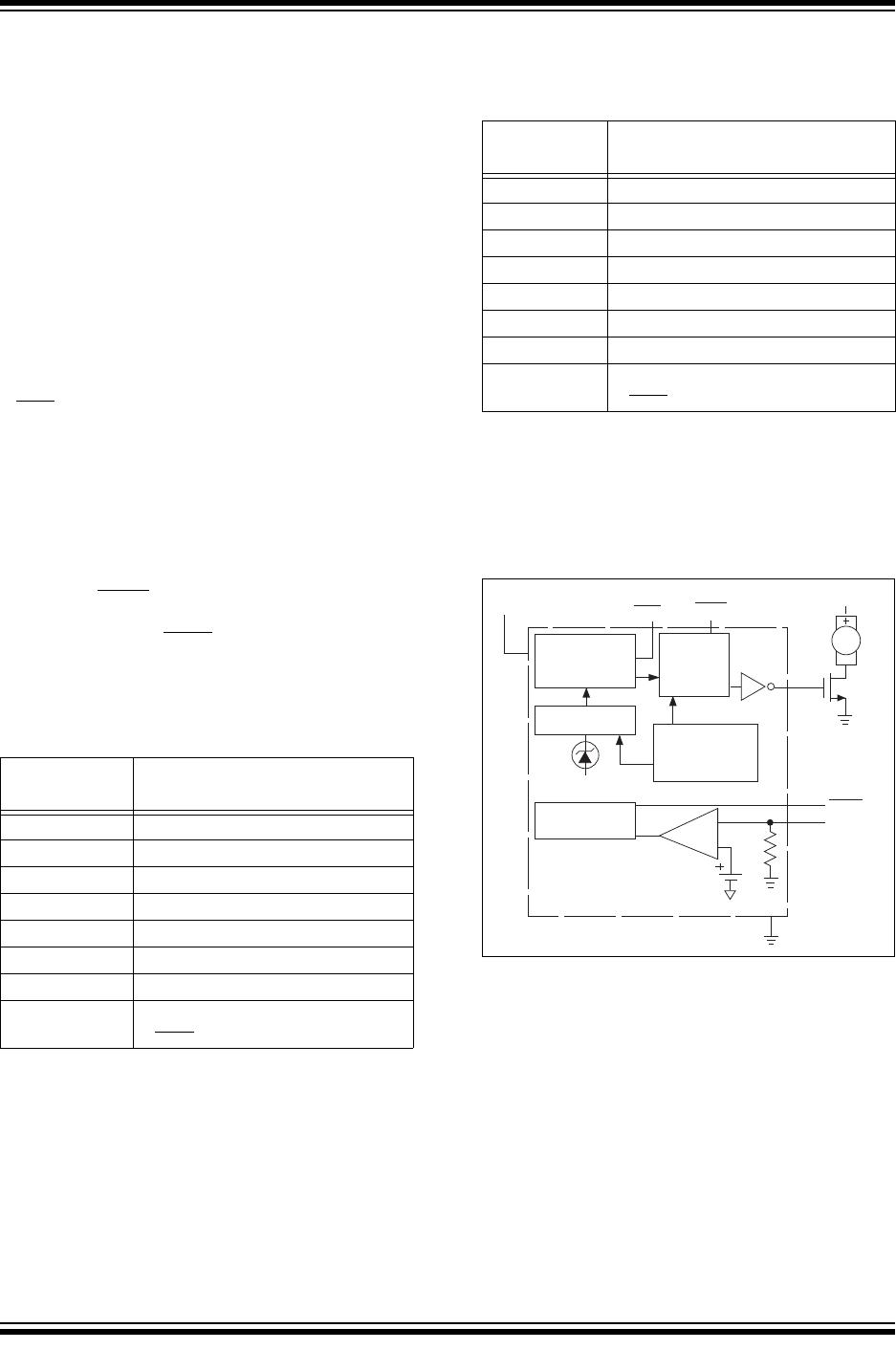
3.3 SENSE Input
(FanSense™ Technology)
The SENSE input, Pin 5, is connected to a low value
current sensing resistor in the ground return leg of the
fan circuit through the capacitor. During normal fan
operation, commutation occurs as each pole of the fan
is energized. This causes brief interruptions in the fan
current, seen as pulses across the sense resistor. If the
device is not in Shutdown mode, and pulses are not
appearing at the SENSE input, a FAULT exists. The
short, rapid change in fan current (high di/dt) causes a
corresponding dv/dt across the sense resistor, R
SENSE
.
The waveform on R
SENSE
is differentiated and con-
verted to a logic-level pulse-train by C
SENSE
and the
internal signal processing circuitry. The presence and
frequency of this pulse-train is a direct indication of fan
operation.
3.4 FAULT
This pin goes low to indicate a fan FAULT condition.
Pulses appearing at SENSE pin due to the PWM turn-
ing on are blanked and the remaining pulses are
filtered by a Missing Pulse Detector. If consecutive
pulses are not detected for 32 PWM cycles (about 2
sec), the PWM is Low and FAULT
goes low. FAULT can
be disabled by momentarily toggling SHDN
or V
DD
pin,
or cycling system power. FAULT
remains high during
Shutdown mode.
3.5 Over-Temperature Alert (T
OVER
)
This pin goes low when the T
H
set point is exceeded
by 10°C (typical). This indicates that the fan is at
maximum drive, and the potential exists for system
overheating: either heat dissipation in the system has
gone beyond the cooling system's design limits, or
some FAULT exists such as fan bearing failure or an
airflow obstruction. This output may be treated as a
“System Overheat” warning and used to trigger system
shutdown, or bring other fans to full speed in the
system. The fan will continue to run at 100% speed
while T
OVER
is asserted. Built-in hysteresis prevents
T
OVER
from “chattering” when measured temperature
is at or near the T
H
+ 10°C trip point. As temperature
falls through the T
H
+ 10°C trip point, hysteresis
maintains the T
OVER
output low until measured
temperature is 5°C above the trip point setting.
3.6 Shutdown (SHDN)
The fan can be unconditionally shutdown by pulling low
the SHDN
pin. During shutdown, FAULT output is high
and PWM output is low. This is ideal for notebook
computers and other portable applications when you
need to change batteries and must not have the fan
running at that time. Thermal monitoring and T
OVER
are
still in operation during shutdown. I
DD
shutdown current
is around 50A.
3.7 Auto-Shutdown Mode
The TC653 has auto-shutdown. If the temperature is
below the factory set point at minimum speed (T
L
),
PWM is low and the fan is automatically shut off (Auto-
shutdown mode). This feature is ideal for notebook
computers and other portable applications that need to
conserve as much battery power as possible and thus
run a fan when it is only absolutely needed. The TC653
will continue to be active so as to monitor temperature
for T
OVER
. The TC653 exits Auto-shutdown mode
when the temperature rises above the factory set point
(T
1
).
3.8 Temperature Selection Guide
(Minimum Fan Speed/Full Speed)
The five temperature regions defined by the six
thresholds are defined in the TC652/TC653 by means
of factory trimming. Once a T
L
and T
H
are set, the T
1
T
4
thresholds are automatically equally spaced
between T
L
and T
H
.

TC652ACVUATR

Mfr. #:
Manufacturer:
Microchip Technology
Description:
Motor / Motion / Ignition Controllers & Drivers W/ Fan Flt & Over T
Lifecycle:
New from this manufacturer.
Delivery:
DHL FedEx Ups TNT EMS
Payment:
T/T Paypal Visa MoneyGram Western Union