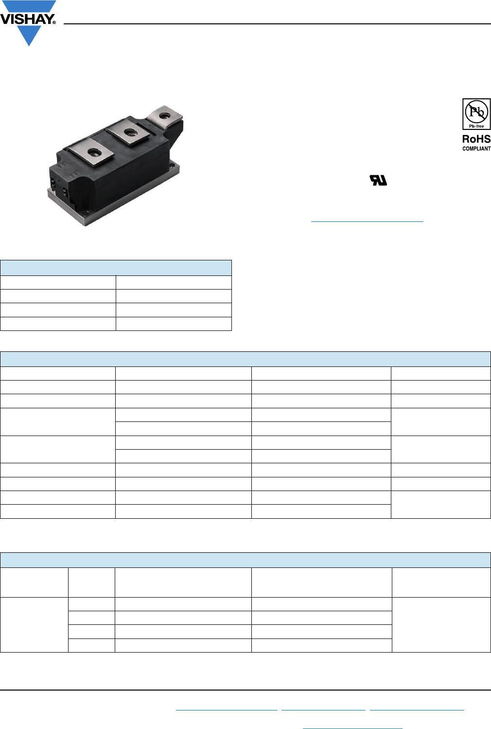
VS-VSKT500-..PbF, VS-VSKH500-..PbF, VS-VSKL500-..PbF
www.vishay.com
Vishay Semiconductors
Revision: 05-Dec-16
2
Document Number: 94420
For technical questions within your region: DiodesAmericas@vishay.com
, DiodesAsia@vishay.com, DiodesEurope@vishay.com
THIS DOCUMENT IS SUBJECT TO CHANGE WITHOUT NOTICE. THE PRODUCTS DESCRIBED HEREIN AND THIS DOCUMENT
ARE SUBJECT TO SPECIFIC DISCLAIMERS, SET FORTH AT www.vishay.com/doc?91000
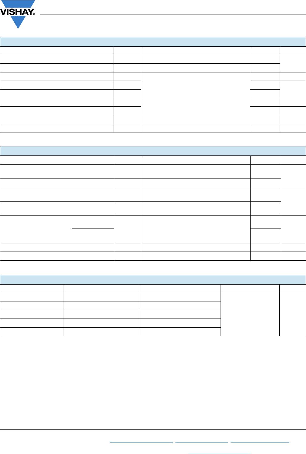
ON-STATE CONDUCTION
PARAMETER SYMBOL TEST CONDITIONS VALUES UNITS
Maximum average on-state current
at case temperature
I
T(AV),
I
F(AV)
180° conduction, half sine wave
500 A
82 °C
Maximum RMS on-state current I
T(RMS)
180° conduction, half sine wave at T
C
= 82 °C 785 A
Maximum peak, one-cycle,
non-repetitive on-state surge current
I
TSM,
I
FSM
t = 10 ms
No voltage
reapplied
Sinusoidal
half wave,
initial T
J
= T
J
maximum
17.8
kA
t = 8.3 ms 18.7
t = 10 ms
100 % V
RRM
reapplied
15.0
t = 8.3 ms 15.7
Maximum I
2
t for fusing I
2
t
t = 10 ms
No voltage
reapplied
1591
kA
2
s
t = 8.3 ms 1452
t = 10 ms
100 % V
RRM
reapplied
1125
t = 8.3 ms 1027
Maximum I
2
t for fusing I
2
t t = 0.1 ms to 10 ms, no voltage reapplied 15 910 kA
2
s
Low level value or threshold voltage V
T(TO)1
(16.7 % x x I
T(AV)
< I < x I
T(AV)
), T
J
= T
J
maximum 0.85
V
High level value of threshold voltage V
T(TO)2
(I > x I
T(AV)
), T
J
= T
J
maximum 0.93
Low level value on-state slope resistance r
t1
(16.7 % x x I
T(AV)
< I < x I
T(AV)
), T
J
= T
J
maximum 0.36
m
High level value on-state slope resistance r
t2
(I > x I
T(AV)
), T
J
= T
J
maximum 0.32
Maximum on-state voltage drop V
TM
I
pk
= 1500 A, T
J
= 25 °C, t
p
= 10 ms sine pulse 1.50 V
Maximum forward voltage drop V
FM
I
pk
= 1500 A, T
J
= 25 °C, t
p
= 10 ms sine pulse 1.50 V
Maximum holding current I
H
T
J
= 25 °C, anode supply 12 V resistive load
500
mA
Maximum latching current I
L
1000
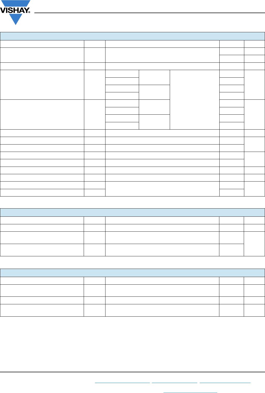
SWITCHING
PARAMETER SYMBOL TEST CONDITIONS VALUES UNITS
Maximum rate of rise of turned-on current dI/dt T
J
= T
J
maximum, I
TM
= 400 A, V
DRM
applied 1000 A/μs
Typical delay time t
d
Gate current 1 A, dI
g
/dt = 1 A/μs
V
d
= 0.67 % V
DRM
, T
J
= 25 °C
2.0
μs
Typical turn-off time t
q
I
TM
= 750 A; T
J
= T
J
maximum, dI/dt = - 60 A/μs,
V
R
= 50 V, dV/dt = 20 V/μs, gate 0 V 100
200
BLOCKING
PARAMETER SYMBOL TEST CONDITIONS VALUES UNITS
Maximum critical rate of rise
of off-state voltage
dV/dt T
J
= 130 °C, linear to V
D
= 80 % V
DRM
1000 V/μs
RMS insulation voltage V
INS
t = 1 s 3000 V
Maximum peak reverse and
off-state leakage current
I
RRM
,
I
DRM
T
J
= T
J
maximum, rated V
DRM
/V
RRM
applied 100 mA