8
COMMERCIAL AND INDUSTRIAL
TEMPERATURE RANGES
IDT72V01/72V02/72V03/72V04/72V05/72V06 3.3V ASYNCHRONOUS FIFO
512 x 9, 1,024 x 9, 2,048 x 9, 4,096 x 9, 8,192 x 9 and 16,384 x 9
OPERATING MODES:
Care must be taken to assure that the appropriate flag is monitored by each
system (i.e. FF is monitored on the device where W is used; EF is monitored
on the device where R is used). For additional information, refer to Tech Note
8: Operating FIFOs on Full and Empty Boundary Conditions and Tech Note
6: Designing with FIFOs.
SINGLE DEVICE MODE
A single IDT72V01/72V02/72V03/72V04/72V05/72V06 may be used
when the application requirements are for 512/1,024/2,048/4,096/8,192/
16,384 words or less. These devices are in a Single Device Configuration when
the Expansion In ( XI ) control input is grounded (see Figure 12).
These FIFOs can easily be adapted to applications when the requirements
are for greater than 512/1,024/2,048/4,096/8,192/16,384 words. Figure 14
demonstrates Depth Expansion using three IDT72V01/72V02/72V03/72V04/
72V05/72V06s. Any depth can be attained by adding additional IDT72V01/
72V02/72V03/72V04/72V05/72V06s. These devices operate in the Depth
Expansion mode when the following conditions are met:
1. The first device must be designated by grounding the First Load ( FL ) control
input.
2. All other devices must have FL in the HIGH state.
3. The Expansion Out ( XO ) pin of each device must be tied to the Expansion
In ( XI ) pin of the next device. See Figure 14.
4. External logic is needed to generate a composite Full Flag ( FF ) and Empty
Flag ( EF ). This requires the ORing of all EFs and ORing of all FFs (i.e.
all must be set to generate the correct composite FF or EF). See Figure 14.
5. The Retransmit ( RT ) function and Half-Full Flag ( HF ) are not available
in the Depth Expansion Mode.
For additional information, refer to Tech Note 9: Cascading FIFOs or FIFO
Modules.
USAGE MODES:
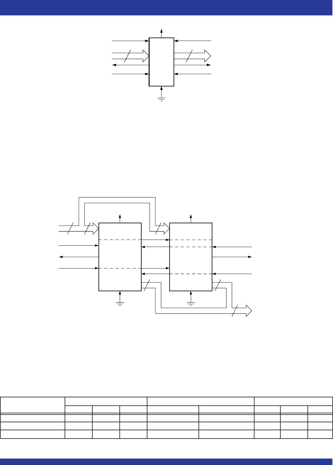
WIDTH EXPANSION
Word width may be increased simply by connecting the corresponding input
control signals of multiple devices. Status flags (EF, FF and HF) can be detected
from any one device. Figure 13 demonstrates an 18-bit word width by using
two IDT72V01/72V02/72V03/72V04/72V05/72V06s. Any word width can be
attained by adding additional IDT72V01/72V02/72V03/72V04/72V05/72V06s
(Figure 13).
BIDIRECTIONAL OPERATION
Applications which require data buffering between two systems (each
system capable of Read and Write operations) can be achieved by pairing
IDT72V01/72V02/72V03/72V04/72V05/72V06s as shown in Figure 16. Both
Depth Expansion and Width Expansion may be used in this mode.
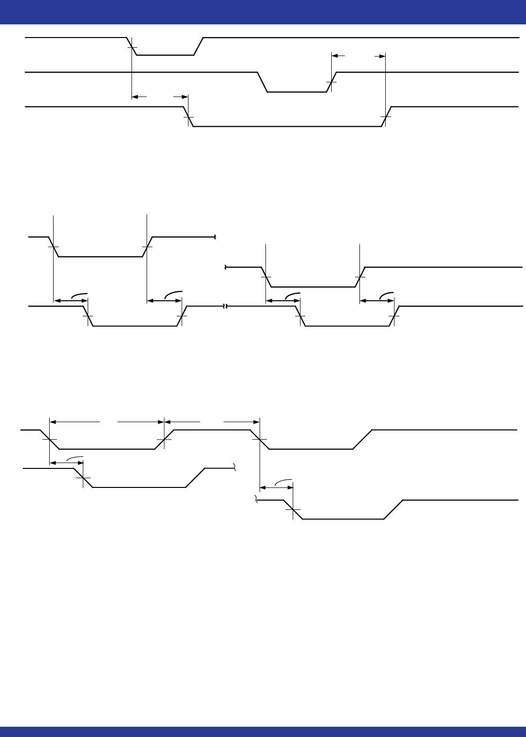
DATA FLOW-THROUGH
Two types of flow-through modes are permitted, a read flow-through and
write flow-through mode. For the read flow-through mode (Figure 17), the FIFO
permits a reading of a single word after writing one word of data into an empty
FIFO. The data is enabled on the bus in (tWEF + tA) ns after the rising edge of
W, called the first write edge, and it remains on the bus until the R line is raised
from LOW-to-HIGH, after which the bus would go into a three-state mode after
tRHZ ns. The EF line would have a pulse showing temporary deassertion and
then would be asserted.
In the write flow-through mode (Figure 18), the FIFO permits the writing of
a single word of data immediately after reading one word of data from a full FIFO.
The R line causes the FF to be deasserted but the W line being LOW causes
it to be asserted again in anticipation of a new data word. On the rising edge
of W, the new word is loaded in the FIFO. The W line must be toggled when FF
is not asserted to write new data in the FIFO and to increment the write pointer.