USB-Disk Module
҈
҈҈
҈Plus
AP-UMxxxxXXXXX-XXXXXT
9
© 2014 Apacer Technology, Inc. Rev. 2.2
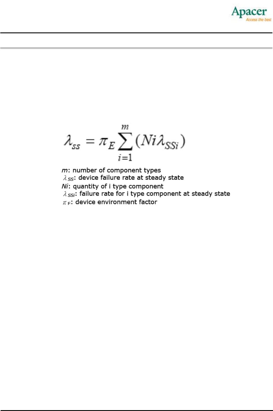
3HUIRUPDQFH5HOLDELOLW\6SHFLILFDWLRQV
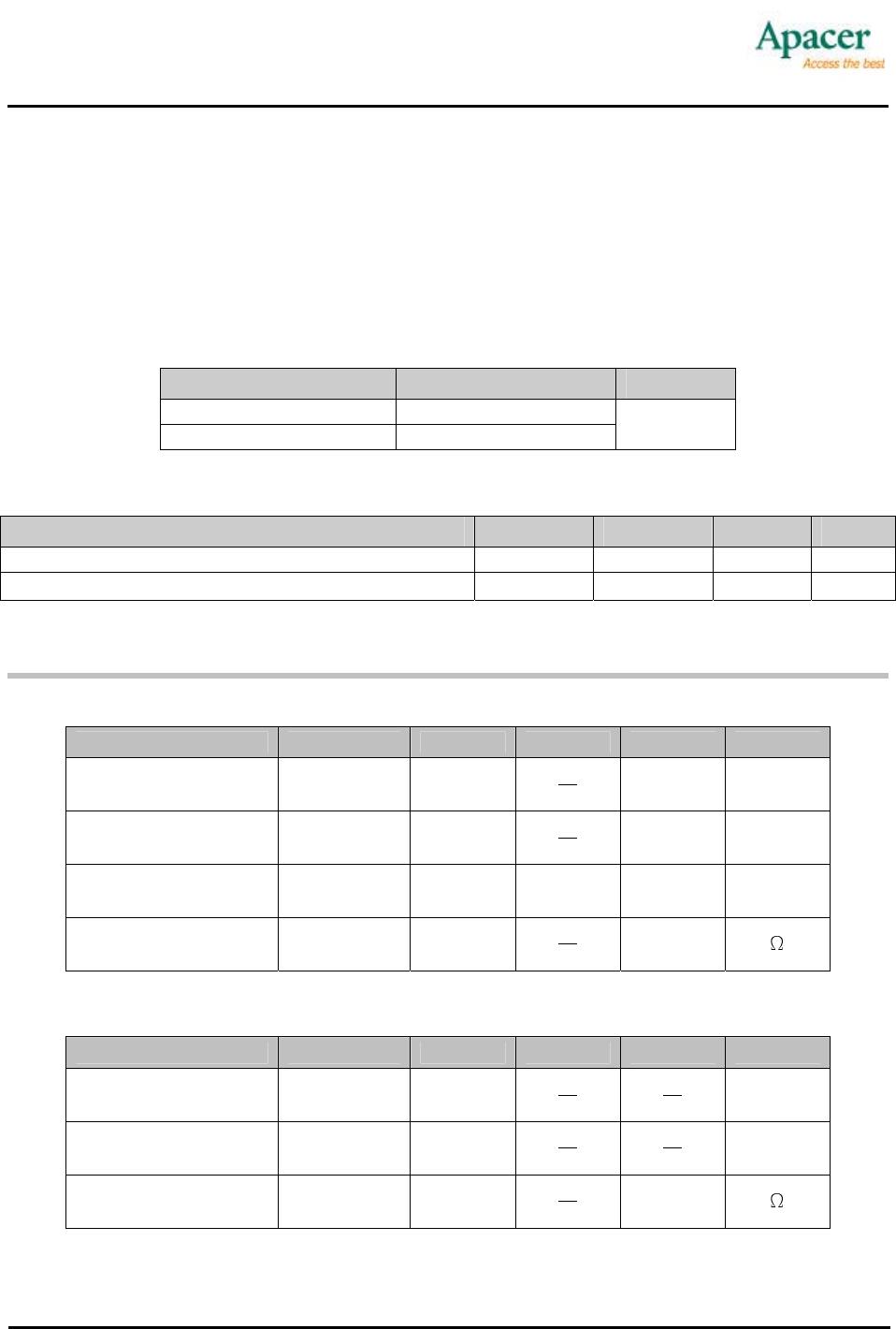
4.1 Capacity Specifications
The USB-Disk Module product family is available as below table matrix.
Table 4-1: Capacity Specification
Density Total Bytes
256MB 254,509,056
512 MB 512,458,752
1GB 1,029,406,720
2GB 2,061,205,504
4GB 4,120,920,064
8GB 8,248,131,584
16GB 16,030,662,656
32GB 32,061,292,544
Notes: the number of total bytes may vary depending on the file system in use.
4.2 Performance Specifications
Table 4-2: Performance Specifications
Capacity
Performance
256 MB 512 MB 1 GB 2 GB 4 GB 8 GB 16 GB 32 GB
Sustained read
(MB/s)
31 31 32 34 28 32 34 31
Sustained write
(MB/s)
10 15 19 19 21 15 22 21
Note: results may vary in real world platforms or flash configurations.
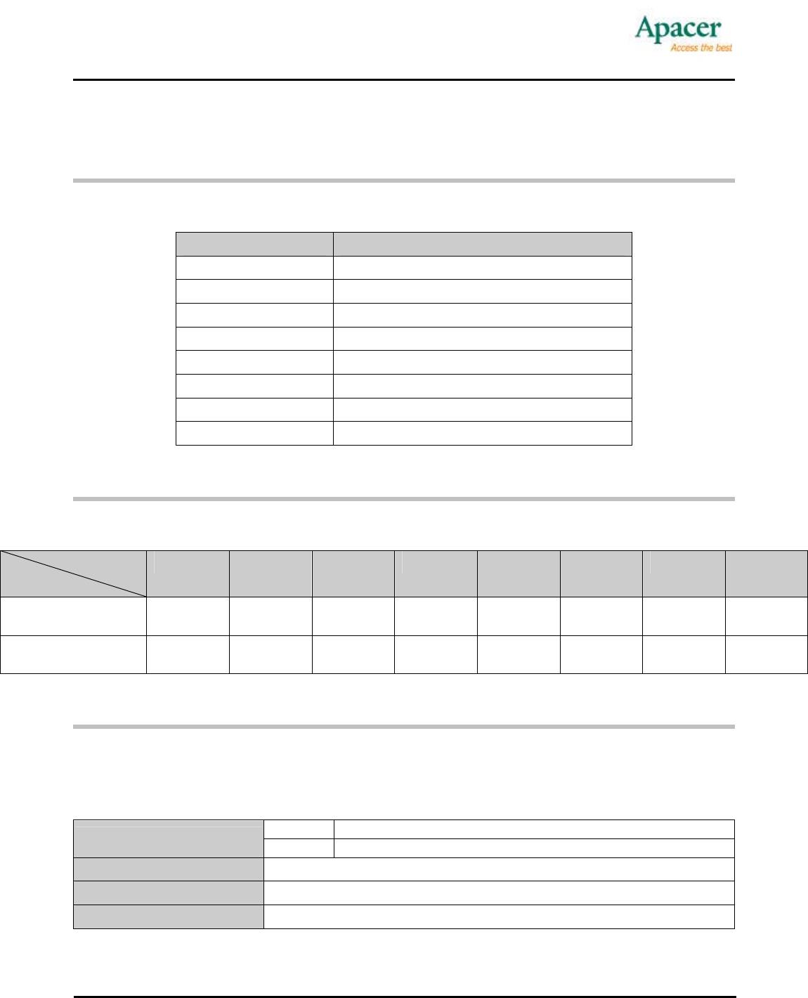
4.3 Environmental Specifications
Environmental specification of the USB-Disk Module (UDM) product family which follows the MIL-STD-
810F standards is available as shown in Table 4-3.
Table 4-3: Environmental Specifications
Operation 0°C to 70°C (Std.); -40°C to 85°C (Ext. Temp.)
Temperature
Storage -40°C to 85°C
Vibration
Sine wave 10 Hz to 500 Hz, 50 m/s
2
, 3 axes (IEC 68-2-6, non-operating)
Shock
Half sine wave 50G, 6 axes, 18 times (IEC 68-2-27, non-operating)
EMC
FCC, CE