Data Sheet ADuM3223/ADuM4223
Rev. I | Page 7 of 20
DIN V VDE V 0884-10 (VDE V 0884-10) INSULATION CHARACTERISTICS
These isolators are suitable for reinforced isolation only within the safety limit data. Maintenance of the safety data is ensured by
protective circuits. The asterisk (*) marking on the package denotes DIN V VDE V 0884-10 approval for a 560 V peak working voltage.
Table 8. ADuM3223 VDE Characteristics
Description Conditions Symbol Characteristic Unit
Installation Classification per DIN VDE 0110
For Rated Mains Voltage ≤ 150 V rms I to IV
For Rated Mains Voltage ≤ 300 V rms I to III
For Rated Mains Voltage ≤ 400 V rms I to II
Climatic Classification 40/105/21
Pollution Degree per DIN VDE 0110, Table 1
2
Maximum Working Insulation Voltage V
IORM
560 V peak
Input-to-Output Test Voltage, Method B1
V
IORM
× 1.875 = V
pd(m)
, 100% production test,
t
ini
= t
m
= 1 sec, partial discharge < 5 pC
V
pd(m)
1050 V peak
Input-to-Output Test Voltage, Method A
V
IORM
× 1.5 = V
pd(m)
, t
ini
= 60 sec,
t
m
= 10 sec, partial discharge < 5 pC
V
pd(m)
After Environmental Tests Subgroup 1 896 V peak
After Input and/or Safety Test Subgroup 2
and Subgroup 3
V
IORM
× 1.2 = V
pd(m)
, t
ini
= 60 sec,
t
m
= 10 sec, partial discharge < 5 pC
V
pd(m)
672 V peak
Highest Allowable Overvoltage V
IOTM
4242 V peak
Surge Isolation Voltage V
PEAK
= 10 kV, 1.2 μs rise time, 50 μs, 50% fall time V
IOSM
6000 V peak
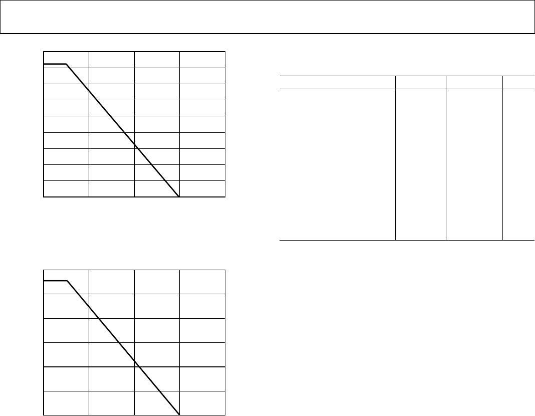
Safety-Limiting Values
Maximum value allowed in the event of a failure
(see Figure 2)
Maximum Junction Temperature T
S
150 °C
Safety Total Dissipated Power P
S
1.64 W
Insulation Resistance at T
S
V
IO
= 500 V R
S
>10
9
Ω
Table 9. ADuM4223 VDE Characteristics
Description Conditions Symbol Characteristic Unit
Installation Classification per DIN VDE 0110
For Rated Mains Voltage ≤ 150 V rms I to IV
For Rated Mains Voltage ≤ 300 V rms I to III
For Rated Mains Voltage ≤ 400 V rms I to II
Climatic Classification 40/105/21
Pollution Degree per DIN VDE 0110, Table 1
2
Maximum Working Insulation Voltage V
IORM
849 V peak
Input-to-Output Test Voltage, Method B1
V
IORM
× 1.875 = V
pd(m)
, 100% production test,
t
ini
= t
m
= 1 sec, partial discharge < 5 pC
V
pd(m)
1592 V peak
Input-to-Output Test Voltage, Method A
V
IORM
× 1.5 = V
pd(m)
, t
ini
= 60 sec, t
m
= 10 sec,
partial discharge < 5 pC
V
pd(m)
After Environmental Tests Subgroup 1 1273 V peak
After Input and/or Safety Test Subgroup 2
and Subgroup 3
V
IORM
× 1.2 = V
pd(m)
, t
ini
= 60 sec, t
m
= 10 sec,
partial discharge < 5 pC
V
pd(m)
1018 V peak
Highest Allowable Overvoltage V
IOTM
7071 V peak
Surge Isolation Voltage V
PEAK
= 10 kV, 1.2 μs rise time, 50 μs, 50% fall time V
IOSM
6000 V peak
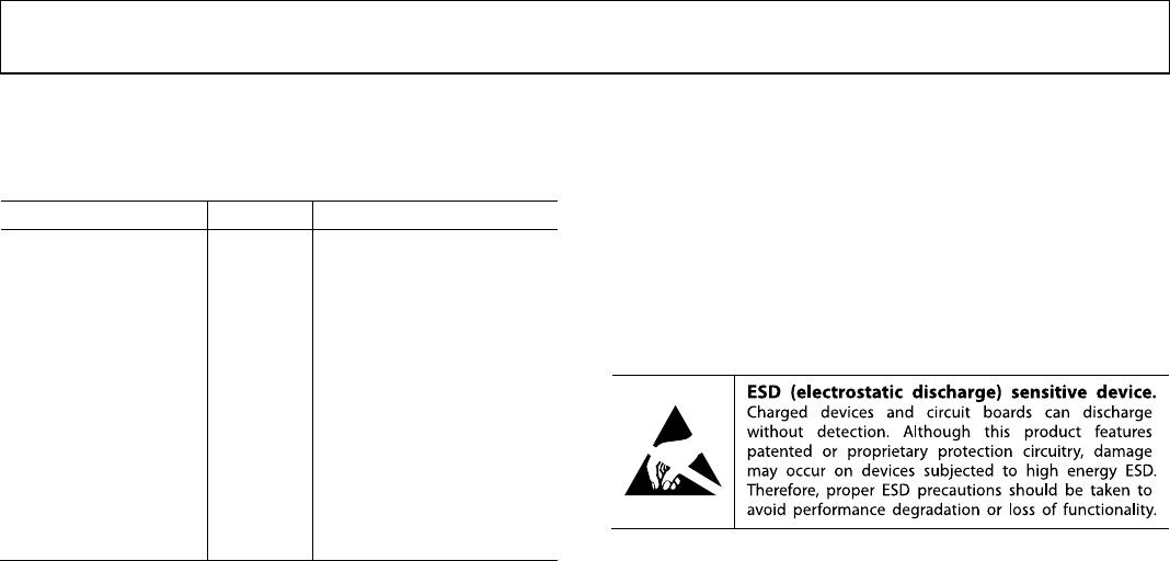
Safety-Limiting Values
Maximum value allowed in the event of a failure
(see Figure 3)
Maximum Junction Temperature T
S
150 °C
Safety Total Dissipated Power P
S
2.77 W
Insulation Resistance at T
S
V
IO
= 500 V R
S
>10
9
Ω