9
COMMERCIAL, INDUSTRIAL AND MILITARY
TEMPERATURE RANGES
IDT7201L/7201LA/7202LA CMOS ASYNCHRONOUS FIFO
256 x 9, 512 x 9 and 1,024 x 9
Figure 9. Half-Full Flag Timing
Figure 10. Expansion Out
Figure 11. Expansion In
OPERATING MODES:
Care must be taken to assure that the appropriate flag is monitored by
each system (i.e. FF is monitored on the device where W is used; EF is monitored
on the device where R is used). For additional information, refer to Tech Note
8: Operating FIFOs on Full and Empty Boundary Conditions and Tech Note
6: Designing with FIFOs.
SINGLE DEVICE MODE
A single IDT7200/7201A/7202A may be used when the application
requirements are for 256/512/1,024 words or less. These devices are in a
Single Device Configuration when the Expansion In (XI) control input is
grounded (see Figure 12).
DEPTH EXPANSION
The IDT7200/7201A/7202A can easily be adapted to applications when
the requirements are for greater than 256/512/1,024 words. Figure 14
demonstrates Depth Expansion using three IDT7200/7201A/7202As. Any
depth can be attained by adding additional IDT7200/7201A/7202As. These
FIFOs operate in the Depth Expansion mode when the following conditions
are met:
1. The first device must be designated by grounding the First Load (FL) control
input.
2. All other devices must have FL in the HIGH state.
3. The Expansion Out (XO) pin of each device must be tied to the Expansion
In (XI) pin of the next device. See Figure 14.
4. External logic is needed to generate a composite Full Flag (FF) and Empty
Flag (EF). This requires the ORing of all EFs and ORing of all FFs (i.e.
all must be set to generate the correct composite FF or EF). See Figure
14.
5. The Retransmit (RT) function and Half-Full Flag (HF) are not available in
the Depth Expansion Mode.
For additional information, refer to Tech Note 9: Cascading FIFOs or
FIFO Modules.
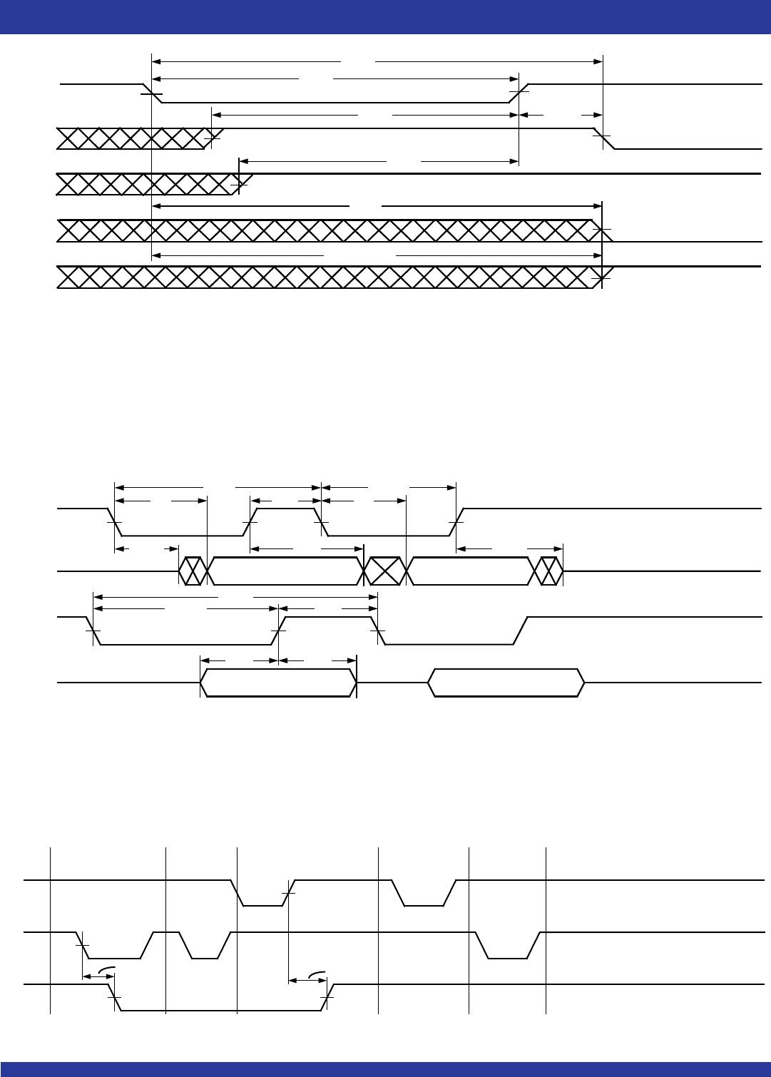
R
W
HF
t
RHF
HALF-FULL OR LESS
MORE THAN HALF-FULL
t
WHF
2679 drw 11
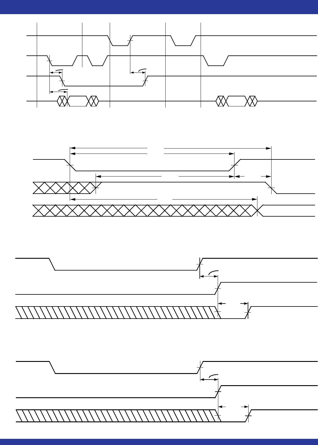
HALF-FULL OR LESS
R
W
XO
2679 drw 12
WRITE TO
LAST PHYSICAL
LOCATION
t
XOL
t
XOH
READ FROM
LAST PHYSICAL
LOCATION
t
XOL
t
XOH
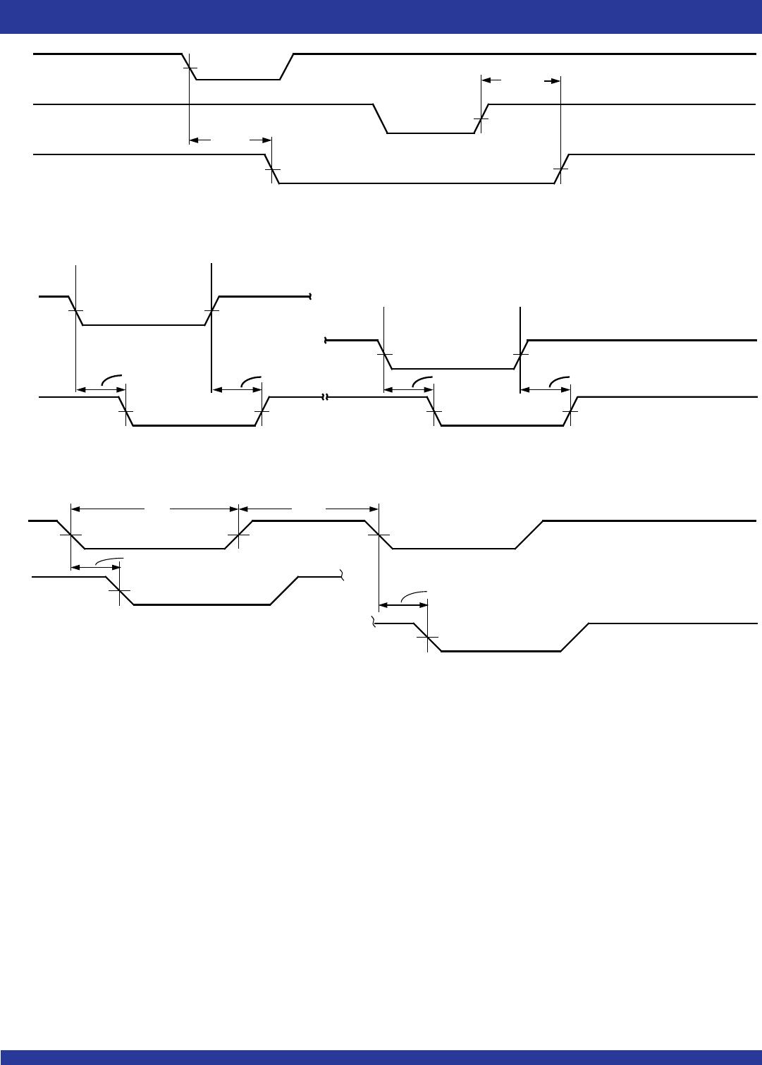
W
R
XI
WRITE TO
FIRST PHYSICAL
LOCATION
t
XIS
READ FROM
FIRST PHYSICAL
LOCATION
t
XIS
t
XI
t
XIR
2679 drw 13