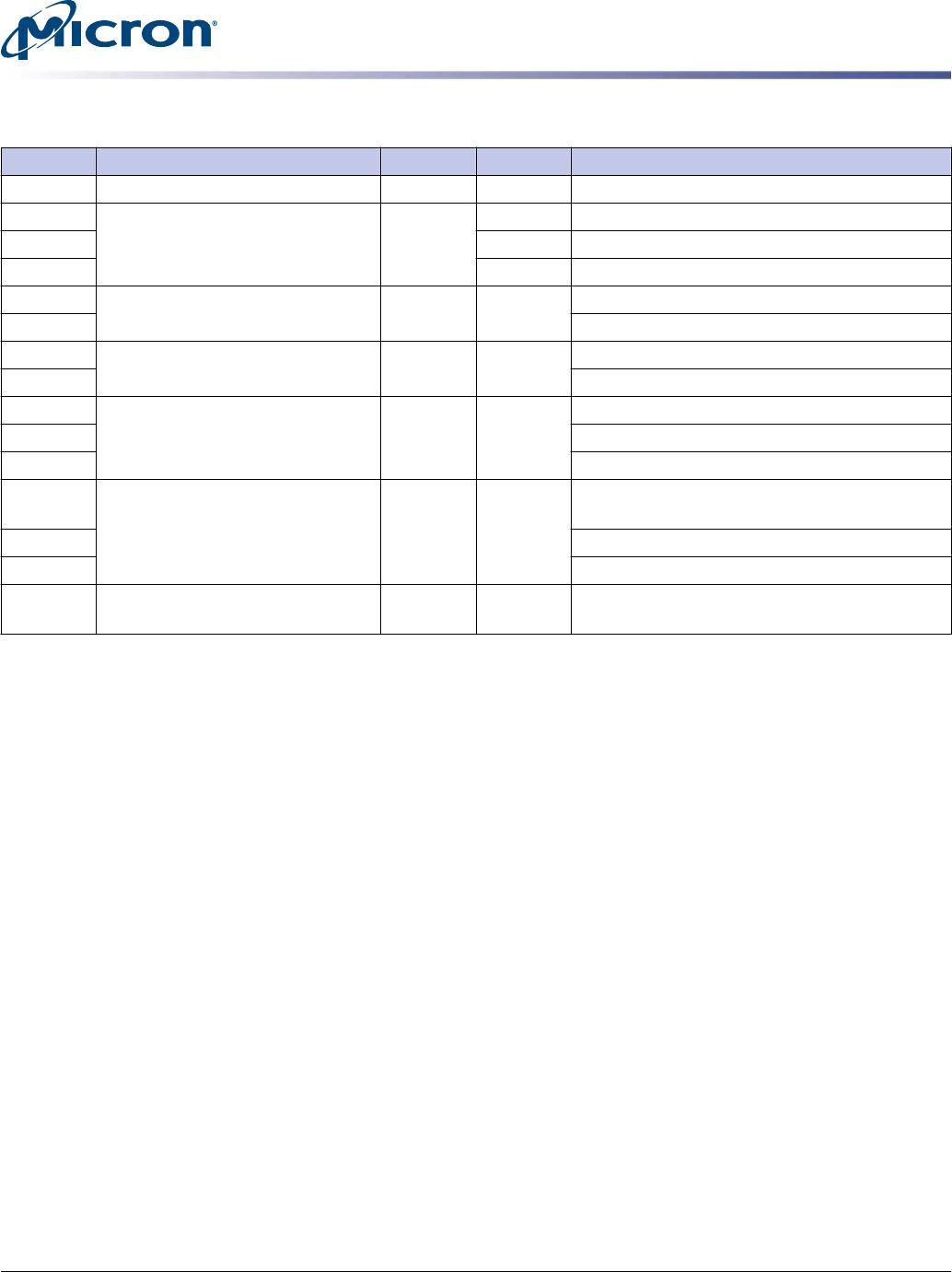
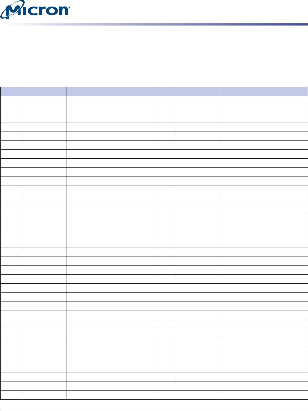
Table 11: Basic Management Command (Address 0x6A) (Continued)
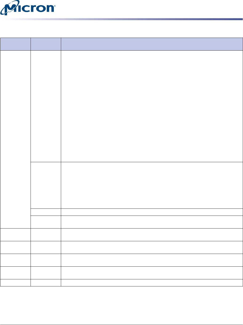
Command
Code Bytes Description
0 03 Composite Temperature (CTemp): This field indicates the current temperature in degrees
Celsius. If a temperature value is reported, it should be the same temperature as the Com-
posite Temperature from the SMART log of hottest controller in the NVM subsystem. The
reported temperature range is vendor specific, and shall not exceed the range -60 to
+127°C. The 8 bit format of the data is shown below.
This field should not report a temperature when that is older than 5 seconds. If recent da-
ta is not available, the NVMe management endpoint should indicate a value of 80h for this
field.
Value: Description
00h-7Eh: Temperature is measured in degrees Celsius (0 to 126C)
7Fh: 127C or higher
80h: No temperature data or temperature data is more the 5 seconds old.
81h: Temperature sensor failure
82h-C3h: Reserved
C4: Temperature is -60C or lower
C5-FFh: Temperature measured in degrees Celsius is represented in twos complement (-1
to -59C)
04 Percentage Drive Life Used (PDLU): Contains a vendor specific estimate of the percent-
age of NVM subsystem NVM life used based on the actual usage and the manufacturer’s
prediction of NVM life. If an NVM subsystem has multiple controllers the highest value is
returned. A value of 100 indicates that the estimated endurance of the NVM in the NVM
subsystem has been consumed, but may not indicate an NVM subsystem failure. The value
is allowed to exceed 100. Percentages greater than 254 shall be represented as 255. This
value should be updated once per power-on hour and equal the Percentage Used value in
the NVMe SMART Health Log Page.
06:05 Reserved: Shall be set to 0000h.
07 PEC: An 8 bit CRC calculated over the slave address, command code, second slave address
and returned data. Algorithm is in SMBus Specifications.
8 08 Length of identification: Indicates number of additional bytes to read before encoun-
tering PEC. Always 22 (16h) in this version of the spec.
10:09 Vendor ID: The 2 byte vendor ID, assigned by the PCI SIG. Should match VID in the Identi-
fy Controller command response. MSB is transmitted first.
30:11 Serial Number: 20 characters that match the serial number in the NVMe Identify Control-
ler command response. First character is transmitted first.
31 PEC: An 8 bit CRC calculated over the slave address, command code, second slave address
and returned data. Algorithm is in SMBus Specifications.
32+ 255:32 Vendor Specific
7100 U.2 NVMe PCIe SSD
Supported Commands
CCMTD-731836775-10498
7100_u2_nvme_pcie_ssd.pdf - Rev. G 03/17 EN
16
Micron Technology, Inc. reserves the right to change products or specifications without notice.
© 2016 Micron Technology, Inc. All rights reserved.
Table 12: Vital Product Data (VPD) (Address 0xA6)
Address Function Type Size (B) Description
0 Class Code RO 3 Device type and programming interface
3 ID RO 2 PCI-SIG Vendor ID
5 20 Serial Number
25 40 Model Number (ASCII string)
65 PCIe Port 0 Capabilities RO 2 Maximum Link Speed
66 Maximum Link Width
67 PCIe Port 1 Capabilities RO 2 Maximum Link Speed
68 Maximum Link Width
69 Initial Power Requirements RO 3 12V power rail initial power requirement (W)
70 Reserved
71 Reserved
72 Maximum Power Requirements RO 3 12V power rail maximum power requirement
(W)
73 Reserved
74 Reserved
75 Capability List Pointer RO 2 16-bit address pointer to start of capability list
(zero means no capability list)
7100 U.2 NVMe PCIe SSD
Supported Commands
CCMTD-731836775-10498
7100_u2_nvme_pcie_ssd.pdf - Rev. G 03/17 EN
17
Micron Technology, Inc. reserves the right to change products or specifications without notice.
© 2016 Micron Technology, Inc. All rights reserved.
Interface Connectors
U.2 Pin Assignments
The U.2, 2.5-inch form factor follows the SFF-8639 specification.
Table 13: PCIe Interface Connector Pin Assignments (U.2 Form Factor)
Pin Name Description Pin Name Description
S1 GND Ground E7 REFCLK0+ PCIe REFCLK 0 p
S2 DNC E8 REFCLK0- PCIe REFCLK 0 p
S3 DNC E9 GND Ground
S4 GND Ground E10 PETp0 PCIe TX Lane 0 p
S5 DNC E11 PETn0 PCIe TX Lane 0 n
S6 DNC E12 GND Ground
S7 GND Ground E13 PERn0 PCIe RX Lane 0 n
E1 REFCLK1+ DNC E14 PERp0 PCIe RX Lane 0 p
E2 REFCLK1- DNC E15 GND Ground
E3 3.3Vaux 3.3V auxiliary power E16 RSVD Reserved
E4 PERST1# DNC S8 GND Ground
E5 PERST0# PCIe Fundamental Reset S9 DNC
E6 RSVD Reserved S10 DNC
P1 DNC S11 GND Ground
P2 DNC S12 DNC
P3 CLKREQ# Clock request S13 DNC
P4 IfDet_N Interface detect S14 GND Ground
P5 GND Ground S15 RSVD Reserved
P6 GND Ground S16 GND Ground
P7 DNC S17 PETp1 PCIe TX Lane 1 p
P8 DNC S18 PETn1 PCIe TX Lane 1 n
P9 DNC S19 GND Ground
P10 PRSNT_N Presence detect S20 PERn1 PCIe RX Lane 1 n
P11 Activity Activity signal from the drive S21 PERp1 PCIe RX Lane 1 p
P12 Hot-Plug Ground S22 GND Ground
P13 +12V_pre 12V power S23 PETp2 PCIe TX Lane 2 p
P14 +12V 12V power S24 PETn2 PCIe TX Lane 2 n
P15 +12V 12V power S25 GND Ground
S26 PERn2 PCIe RX Lane 2 n
S27 PERp2 PCIe RX Lane 2 p
S28 GND Ground
E17 PETp3 PCIe TX Lane 3 p
E18 PETn3 PCIe TX Lane 3 n
E19 GND Ground
7100 U.2 NVMe PCIe SSD
Interface Connectors
CCMTD-731836775-10498
7100_u2_nvme_pcie_ssd.pdf - Rev. G 03/17 EN
18
Micron Technology, Inc. reserves the right to change products or specifications without notice.
© 2016 Micron Technology, Inc. All rights reserved.

MTFDHAK960MCH-1AN15ABYY

Mfr. #:
Manufacturer:
Micron
Description:
SSD 960GB 2.5" MLC NVME 12V
Lifecycle:
New from this manufacturer.
Delivery:
DHL FedEx Ups TNT EMS
Payment:
T/T Paypal Visa MoneyGram Western Union