VS-VSK.166..PbF, VS-VSK.196..PbF, VS-VSK.236..PbF Series
www.vishay.com
Vishay Semiconductors
Revision: 29-Sep-15
2
Document Number: 94357
For technical questions within your region: DiodesAmericas@vishay.com
, DiodesAsia@vishay.com, DiodesEurope@vishay.com
THIS DOCUMENT IS SUBJECT TO CHANGE WITHOUT NOTICE. THE PRODUCTS DESCRIBED HEREIN AND THIS DOCUMENT
ARE SUBJECT TO SPECIFIC DISCLAIMERS, SET FORTH AT www.vishay.com/doc?91000
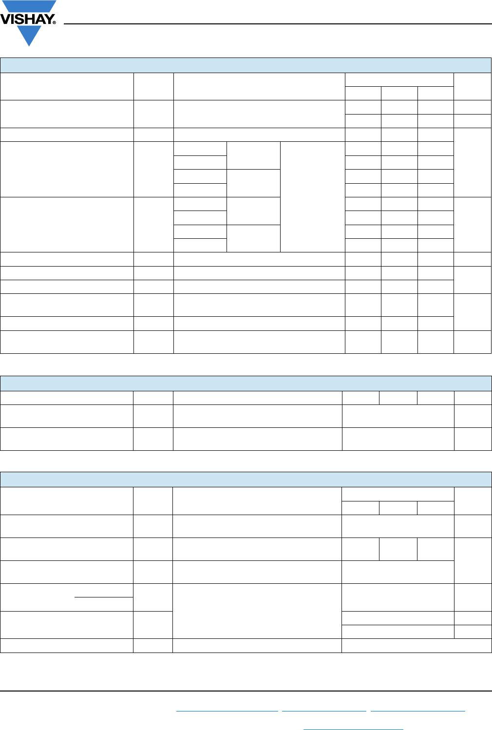
FORWARD CONDUCTION
PARAMETER SYMBOL TEST CONDITIONS
VALUES
UNITS
VSK.166 VSK.196 VSK.236
Maximum average on-state
current at case temperature
I
F(AV)
180° conduction, half sine wave
165 195 230 A
100 100 100 °C
Maximum RMS on-state current I
F(RMS)
260 305 360
A
Maximum peak, one-cycle
on-state, non-repetitive
surge current
I
FSM
t = 10 ms
No voltage
reapplied
Sine half wave,
initial T
J
=
T
J
maximum
4000 4750 5500
t = 8.3 ms 4200 4980 5765
t = 10 ms
100 % V
RRM
reapplied
3350 4000 4630
t = 8.3 ms 3500 4200 4850
Maximum I
2
t for fusing I
2
t
t = 10 ms
No voltage
reapplied
80 113 151
kA
2
s
t = 8.3 ms 73 103 138
t = 10 ms
100 % V
RRM
reapplied
56 80 107
t = 8.3 ms 52 73 98
Maximum I
2
t for fusing I
2
t t = 0.1 ms to 10 ms, no voltage reapplied 798 1130 1516 kA
2
s
Low level value of threshold voltage V
F(TO)1
(16.7 % x x I
F(AV)
< I < x I
F(AV)
), T
J
maximum 0.73 0.69 0.7
V
High level value of threshold voltage V
F(TO)2
(I > x I
F(AV)
), T
J
maximum 0.88 0.78 0.83
Low level value on-state
slope resistance
r
t1
(16.7 % x x I
F(AV)
< I < x I
F(AV)
), T
J
maximum 1.5 1.3 1.2
m
High level value on-state
r
t2
(I > x I
F(AV)
), T
J
maximum 1.26 1.2 1.07
Maximum forward voltage drop V
FM
I
FM
= x I
F(AV)
, T
J
= 25 °C, 180° conduction
Average power = V
F(TO)
x I
F(AV)
+ r
f
x (I
F(RMS)
)
2
1.43 1.38 1.46 V
BLOCKING
PARAMETER SYMBOL TEST CONDITIONS VSK.166 VSK.196 VSK.236 UNITS
Maximum peak reverse and
off-state leakage current
I
RRM
T
J
= 150 °C 20 mA
RMS insulation voltage V
INS
50 Hz, circuit to base, all terminals shorted,
t = 1 s
3500 V
THERMAL AND MECHANICAL SPECIFICATIONS
PARAMETER SYMBOL TEST CONDITIONS
VALUES
UNITS
VSK.166 VSK.196 VSK.236
Maximum junction operating and
storage temperature range
T
J
, T
Stg
-40 to +150 °C
Maximum thermal resistance,
junction to case per junction
R
thJC
DC operation 0.2 0.16 0.14
K/W
Maximum thermal resistance,
case to heatsink per module
R
thCS
Mounting surface smooth, flat and greased 0.05
Mounting
torque ± 10 %
IAP to heatsink
A mounting compound is recommended and
the torque should be rechecked after a period
of 3 hours to allow for the spread of
the compound. Lubricated threads.
4 to 6 Nm
busbar to IAP
Approximate weight
200 g
7.1 oz.
Case style INT-A-PAK