R07DS0255EJ0200 Rev.2.00 Page 1 of 8
Feb 25, 2013
Preliminary Datasheet
BCR4CM-16LH
800V - 4A - Triac
Medium Power Use
Features
I
T (RMS)
: 4 A
V
DRM
: 800 V
I
FGTI
, I
RGTI
, I
RGT III
: 35 mA or 10mA(I
GT
item:1)
High Commutation
The Product guaranteed maximum junction
temperature 150C
Planar Type
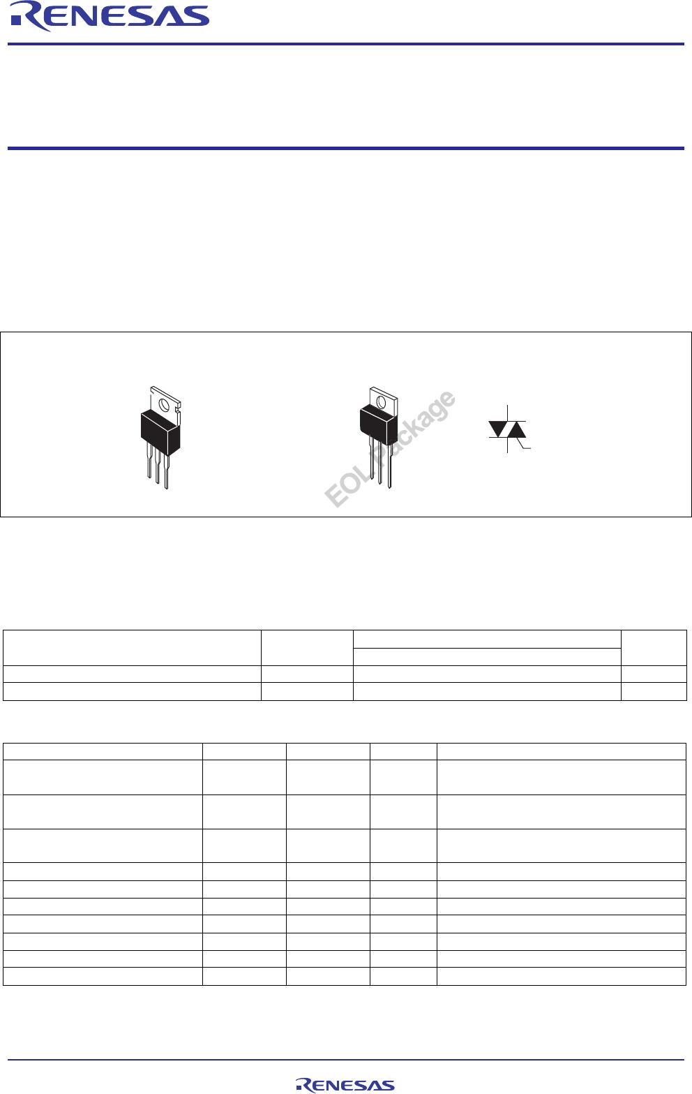
Outline
2
1
3
1. T
1
Terminal
2. T
2
Terminal
3. Gate Terminal
4. T
2
Terminal
4
RENESAS Packa
e code:
-
(
Packa
e name:
TO-220
1
2
3
RENESAS Package code: PRSS0004AG-A
(Package name:
TO-220AB)
Applications
Switching mode power supply, small motor control, heater control, and other general purpose AC power control
applications
Maximum Ratings
Voltage class
Parameter Symbol
16
Unit
Repetitive peak off-state voltage
Note1
V
DRM
800 V
Non-repetitive peak off-state voltage
Note1
V
DSM
960 V
Parameter Symbol Ratings Unit Conditions
RMS on-state current I
T (RMS)
4 A Commercial frequency, sine full wave
360conduction, Tc = 132C
Note3
Surge on-state current I
TSM
30 A 60 Hz sinewave 1 full cycle, peak value,
non-repetitive
I
2
t for fusion I
2
t 3.7 A
2
s Value corresponding to 1 cycle of half
wave 60 Hz, surge on-state current
Peak gate power dissipation P
GM
3 W
Average gate power dissipation P
G (AV)
0.3 W
Peak gate voltage V
GM
10 V
Peak gate current I
GM
2 A
Junction Temperature Tj –40 to +150 C
Storage temperature Tstg –40 to +150 C
Mass — 2.1 g Typical value
R07DS0255EJ0200
Rev.2.00
Feb 25, 2013