Functional Block Diagram
Figure 2: Functional Block Diagram
U1
A0
Serial PD
A1
A2
SA0 SA1
SA2
SDA
SCL
WP
DQ0
DQ1
DQ2
DQ3
DQ4
DQ5
DQ6
DQ7
DQ
DQ
DQ
DQ
DQ
DQ
DQ
DQ
DM/ NF/ CS# DQS DQS#
RDQS RDQS#
DQ
DQ
DQ
DQ
DQ
DQ
DQ
DQ
DQ32
DQ33
DQ34
DQ35
DQ36
DQ37
DQ38
DQ39
DM/ NF/ CS# DQS DQS#
RDQS RDQS#
RS0#
DQS0
DQS0#
DM0/DQS9
NF/DQS9#
U6
DQS4
DQS4#
DM4/DQS13
NF/DQS13#
DQS1
DQS1#
DM1/DQS10
NF/DQS10#
DQS5
DQS5#
DM5/DQS14
NF/DQS14#
DQS2
DQS2#
DM2/DQS11
NF/DQS11#
DQS6
DQS6#
DM6/DQS15
NF/DQS15#
DQS3
DQS3#
DM3/DQS12
NF/DQS12#
DQS7
DQS7#
DM7/DQS16
NF/DQS16#
DQS8
DQS8#
DM8/DQS17
NF/DQS17#
DQ
DQ
DQ
DQ
DQ
DQ
DQ
DQ
DQ8
DQ9
DQ10
DQ11
DQ12
DQ13
DQ14
DQ15
DM/ NF/ CS# DQS DQS#
RDQS RDQS#
DQ
DQ
DQ
DQ
DQ
DQ
DQ
DQ
DQ40
DQ41
DQ42
DQ43
DQ44
DQ45
DQ46
DQ47
DM/ NF/ CS# DQS DQS#
RDQS RDQS#
U9
U13
DQ
DQ
DQ
DQ
DQ
DQ
DQ
DQ
DQ16
DQ17
DQ18
DQ19
DQ20
DQ21
DQ22
DQ23
DM/ NF/ CS# DQS DQS#
RDQS RDQS#
DQ
DQ
DQ
DQ
DQ
DQ
DQ
DQ
DQ48
DQ49
DQ50
DQ51
DQ52
DQ53
DQ54
DQ55
DM/ NF/ CS# DQS DQS#
RDQS RDQS#
DQ
DQ
DQ
DQ
DQ
DQ
DQ
DQ
DQ24
DQ25
DQ26
DQ27
DQ28
DQ29
DQ30
DQ31
DM/ NF/ CS# DQS DQS#
RDQS RDQS#
DQ
DQ
DQ
DQ
DQ
DQ
DQ
DQ
DQ56
DQ57
DQ58
DQ59
DQ60
DQ61
DQ62
DQ63
DM/ NF/ CS# DQS DQS#
RDQS RDQS#
DQ
DQ
DQ
DQ
DQ
DQ
DQ
DQ
CB0
CB1
CB2
CB3
CB4
CB5
CB6
CB7
DM/ NF/ CS# DQS DQS#
RDQS RDQS#
U2
U3
U12
U8
U7
R
E
G
I
S
T
E
R
S
PLL
U10
S0#
BA[2:0]
A[13;0]
RAS#
CAS#
WE#
CKE0
ODT0
PAR_IN
RESET#
RS0#: DDR2 SDRAM
RBA[2/1:0]: DDR2 SDRAM
RA[13:0]: DDR2 SDRAM
RRAS#: DDR2 SDRAM
RCAS#: DDR2 SDRAM
RWE#: DDR2 SDRAM
RCKE0: DDR2 SDRAM
RODT0: DDR2 SDRAM
ERR_OUT
CK0
CK0#
DDR2 SDRAM
DDR2 SDRAM
DDR2 SDRAM
DDR2 SDRAM
DDR2 SDRAM
DDR2 SDRAM
DDR2 SDRAM
DDR2 SDRAM
DDR2 SDRAM
REGISTER x2
RESET#
U5
U4, U11
VREF
VSS
DDR2 SDRAM
DDR2 SDRAM
VDD
DDR2 SDRAM
VDDSPD
Serial PD
VDDQ
DDR2 SDRAM
VSS
512MB, 1GB (x72, ECC, SR) 244-Pin DDR2 VLP Mini-RDIMM
Functional Block Diagram
PDF: 09005aef83d09b45
hvf9c64_128x72pkz.pdf - Rev. C 4/14 EN
7
Micron Technology, Inc. reserves the right to change products or specifications without notice.
© 2009 Micron Technology, Inc. All rights reserved.
General Description
DDR2 SDRAM modules are high-speed, CMOS dynamic random access memory mod-
ules that use internally configured 4 or 8-bank DDR2 SDRAM devices. DDR2 SDRAM
modules use DDR architecture to achieve high-speed operation. DDR2 architecture is
essentially a 4n-prefetch architecture with an interface designed to transfer two data
words per clock cycle at the I/O pins. A single read or write access for the DDR2 SDRAM
module effectively consists of a single 4n-bit-wide, one-clock-cycle data transfer at the
internal DRAM core and eight corresponding n-bit-wide, one-half-clock-cycle data
transfers at the I/O pins.
DDR2 modules use two sets of differential signals: DQS, DQS# to capture data and CK
and CK# to capture commands, addresses, and control signals. Differential clocks and
data strobes ensure exceptional noise immunity for these signals and provide precise
crossing points to capture input signals. A bidirectional data strobe (DQS, DQS#) is
transmitted externally, along with data, for use in data capture at the receiver. DQS is a
strobe transmitted by the DDR2 SDRAM device during READs and by the memory con-
troller during WRITEs. DQS is edge-aligned with data for READs and center-aligned
with data for WRITEs.
DDR2 SDRAM modules operate from a differential clock (CK and CK#); the crossing of
CK going HIGH and CK# going LOW will be referred to as the positive edge of CK. Com-
mands (address and control signals) are registered at every positive edge of CK. Input
data is registered on both edges of DQS, and output data is referenced to both edges of
DQS, as well as to both edges of CK.
Serial Presence-Detect EEPROM Operation
DDR2 SDRAM modules incorporate serial presence-detect. The SPD data is stored in a
256-byte EEPROM. The first 128 bytes are programmed by Micron to identify the mod-
ule type and various SDRAM organizations and timing parameters. The remaining 128
bytes of storage are available for use by the customer. System READ/WRITE operations
between the master (system logic) and the slave EEPROM device occur via a standard
I
2
C bus using the DIMM’s SCL (clock) SDA (data), and SA (address) pins. Write protect
(WP) is connected to V
SS
, permanently disabling hardware write protection.
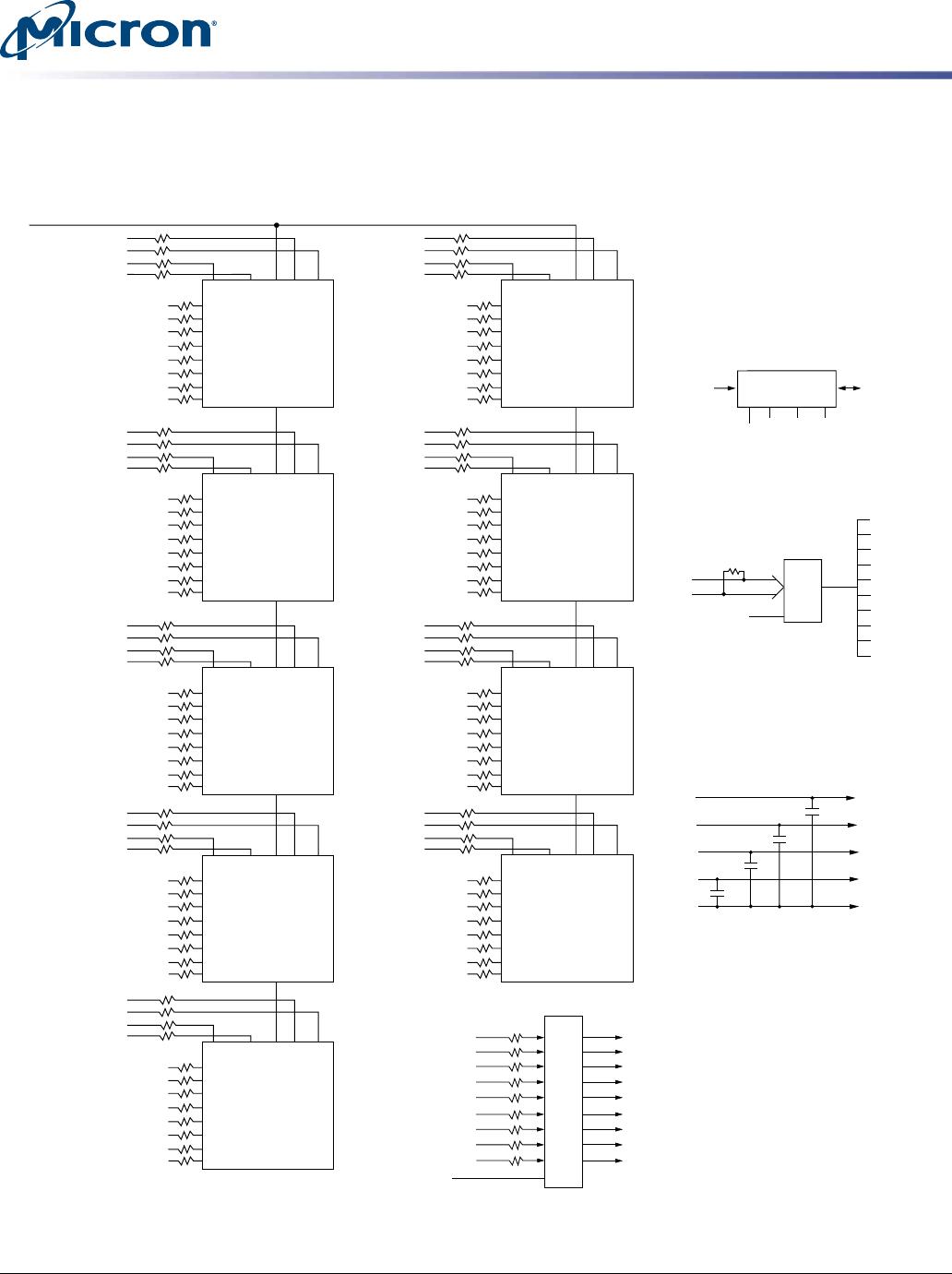
Register and PLL Operation
DDR2 SDRAM modules operate in registered mode, where the command/address input
signals are latched in the registers on the rising clock edge and sent to the DDR2
SDRAM devices on the following rising clock edge (data access is delayed by one clock
cycle). A phase-lock loop (PLL) on the module receives and redrives the differential
clock signals (CK, CK#) to the DDR2 SDRAM devices. The registers and PLL minimize
system and clock loading. PLL clock timing is defined by JEDEC specifications and en-
sured by use of the JEDEC clock reference board. Registered mode will add one clock
cycle to CL.
Parity Operations
The registering clock driver can accept a parity bit from the system’s memory control-
ler, providing even parity for the control, command, and address bus. Parity errors are
flagged on the Err_Out# pin. Systems not using parity are expected to function without
issue if Par_In and Err_Out# are left as no connects (NC) to the system.
512MB, 1GB (x72, ECC, SR) 244-Pin DDR2 VLP Mini-RDIMM
General Description
PDF: 09005aef83d09b45
hvf9c64_128x72pkz.pdf - Rev. C 4/14 EN
8
Micron Technology, Inc. reserves the right to change products or specifications without notice.
© 2009 Micron Technology, Inc. All rights reserved.
Electrical Specifications
Stresses greater than those listed may cause permanent damage to the DRAM devices
on the module. This is a stress rating only, and functional operation of the module at
these or any other conditions above those indicated in each device’s data sheet is not
implied. Exposure to absolute maximum rating conditions for extended periods may
adversely affect reliability.
Table 7: Absolute Maximum Ratings
Symbol Parameter Min Max Units
V
DD
/V
DDQ
V
DD
/V
DDQ
supply voltage relative to V
SS
–0.5 2.3 V
V
IN
, V
OUT
Voltage on any pin relative to V
SS
–0.5 2.3 V
I
I
Input leakage current; Any input 0V V
IN
V
DD
;
V
REF
input 0V V
IN
0.95V (All other pins not under
test = 0V)
Command/address
RAS#, CAS#, WE#, S#,
CKE, ODT, BA
–5 5 µA
CK, CK# –250 250
DM –5 5
I
OZ
Output leakage current; 0V V
OUT
V
DDQ
; DQs and
ODT are disabled
DQ, DQS, DQS# –5 5 µA
I
VREF
V
REF
leakage current; V
REF
= valid V
REF
level –18 18 µA
T
A
Module ambient operating temperature Commercial 0 70 °C
Industrial –40 85 °C
T
C
1
DDR2 SDRAM component case operating tempera-
ture
2
Commercial 0 85 °C
Industrial –40 95 °C
Notes:
1. Refresh rate is required to double when 85°C < T
C
95°C.
2. For further information, refer to technical note TN-00-08: “Thermal Applications,” avail-
able on Micron’s Web site.
512MB, 1GB (x72, ECC, SR) 244-Pin DDR2 VLP Mini-RDIMM
Electrical Specifications
PDF: 09005aef83d09b45
hvf9c64_128x72pkz.pdf - Rev. C 4/14 EN
9
Micron Technology, Inc. reserves the right to change products or specifications without notice.
© 2009 Micron Technology, Inc. All rights reserved.

MT9HVF6472PKZ-667G1

Mfr. #:
Manufacturer:
Micron
Description:
DRAM Module DDR2 SDRAM 512Mbyte 244MiniRDIMM
Lifecycle:
New from this manufacturer.
Delivery:
DHL FedEx Ups TNT EMS
Payment:
T/T Paypal Visa MoneyGram Western Union

Products related to this Datasheet