CMF65300R00FKR6

CMF Industrial
www.vishay.com
Vishay Dale
Revision: 19-Nov-12
1
Document Number: 31018
For technical questions, contact: ff2aresistors@vishay.com
THIS DOCUMENT IS SUBJECT TO CHANGE WITHOUT NOTICE. THE PRODUCTS DESCRIBED HEREIN AND THIS DOCUMENT
ARE SUBJECT TO SPECIFIC DISCLAIMERS, SET FORTH AT www.vishay.com/doc?91000
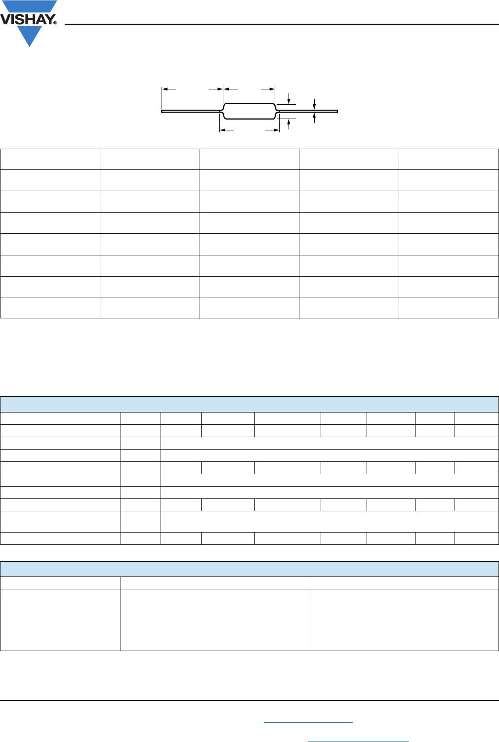
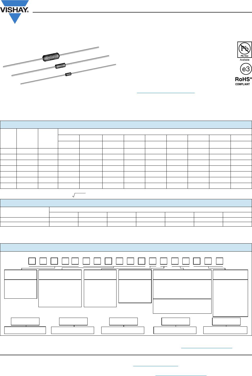
Metal Film Resistors, Industrial, Precision
FEATURES
Small size - conformal coated
Flame retardant epoxy coating
Controlled temperature coefficient
Excellent high frequency characteristics
Exceptionally low noise; typically 0.10 μV/V
Low voltage coefficient to ± 5 ppm/V
Special tolerance and or TC matching
available on request
Material categorization: For definitions of
compliance please see
www.vishay.com/doc?99912
Note
* Lead (Pb)-containing terminations are not RoHS-compliant.
Exemptions may apply.
Vishay Dale Model CMF is also available as Military Qualified Styles RN and RL. See appropriate catalog or web page for the
MIL-SPEC ratings/attributes. (Except for marking, the Industrial and Military versions are exactly the same. Depending upon
stock, military marked parts may be supplied as industrial rated parts).
Note
(1)
Continuous working voltage shall be or maximum working voltage, whichever is less
Note
(2)
See the load life shift due to power and derating table for a summary of the more common combinations of power rating, case size and
ambient operating temperature that prevail in various industrial and military resistor specifications. The “performance” table quantifies the
load life stability under these combinations.
Notes
(3)
Tolerances of ± 0.5 % (D), ± 0.25 % (C) and ± 0.1 % (B) are available only in 50 ppm and 25 ppm temperature coefficients.
For additional information on packaging, refer to the Through-Hole Resistor Packaging document (www.vishay.com/doc?31544).
STANDARD ELECTRICAL SPECIFICATIONS
GLOBAL
MODEL
HISTORICAL
MODEL
MAXIMUM
WORKING
VOLTAGE
(1)
V
RESISTANCE RANGE
0.1 % to 1 % 0.1 % to 0.5 % 1 % to 5 % 1 % 2 %, 5 % 1 % 2 %, 5 % 1 % 2 %, 5 %
25 ppm/°C 50 ppm/°C 50 ppm/°C 100 ppm/°C 100 ppm/°C 150 ppm/°C 150 ppm/°C 200 ppm/°C 200 ppm/°C
CMF50 CMF-50 200 10 to 2.5M 10 to 2.5M 10 to 2.5M 10 to 2.5M 10 to 2.5M 10 to 22M 10 to 22M 10 to 22M 10 to 22M
CMF55 CMF-55 250 10 to 2.5M 10 to 2.5M 10 to 5M 1 to 22.1M 1 to 22.1M 0.5 to 50M 0.5 to 50M 0.5 to 50M 0.1 to 50M
CMF60 CMF-60 500 10 to 2.5M 10 to 2.5M 10 to 10M 1 to 10M 1 to 10M 0.5 to 10M 0.5 to 10M 0.5 to 10M 0.1 to 10M
CMF65 CMF-65 500 10 to 2.5M 10 to 2.5M 10 to 10M 1 to 15M 1 to 15M 0.5 to 22M 0.5 to 22M 0.5 to 22M 0.1 to 22M
CMF70 CMF-70 500 10 to 2.5M 10 to 2.5M 10 to 10M 1 to 15M 1 to 15M 1 to 22M 1 to 22M 1 to 22M 1 to 22M
CMF07 CMF-07 250 - - - - 5 to 5M - 1 to 5M - 1 to 5M
CMF20 CMF-20 500 - - - - 5 to 10M - 1 to 10M - 1 to 10M
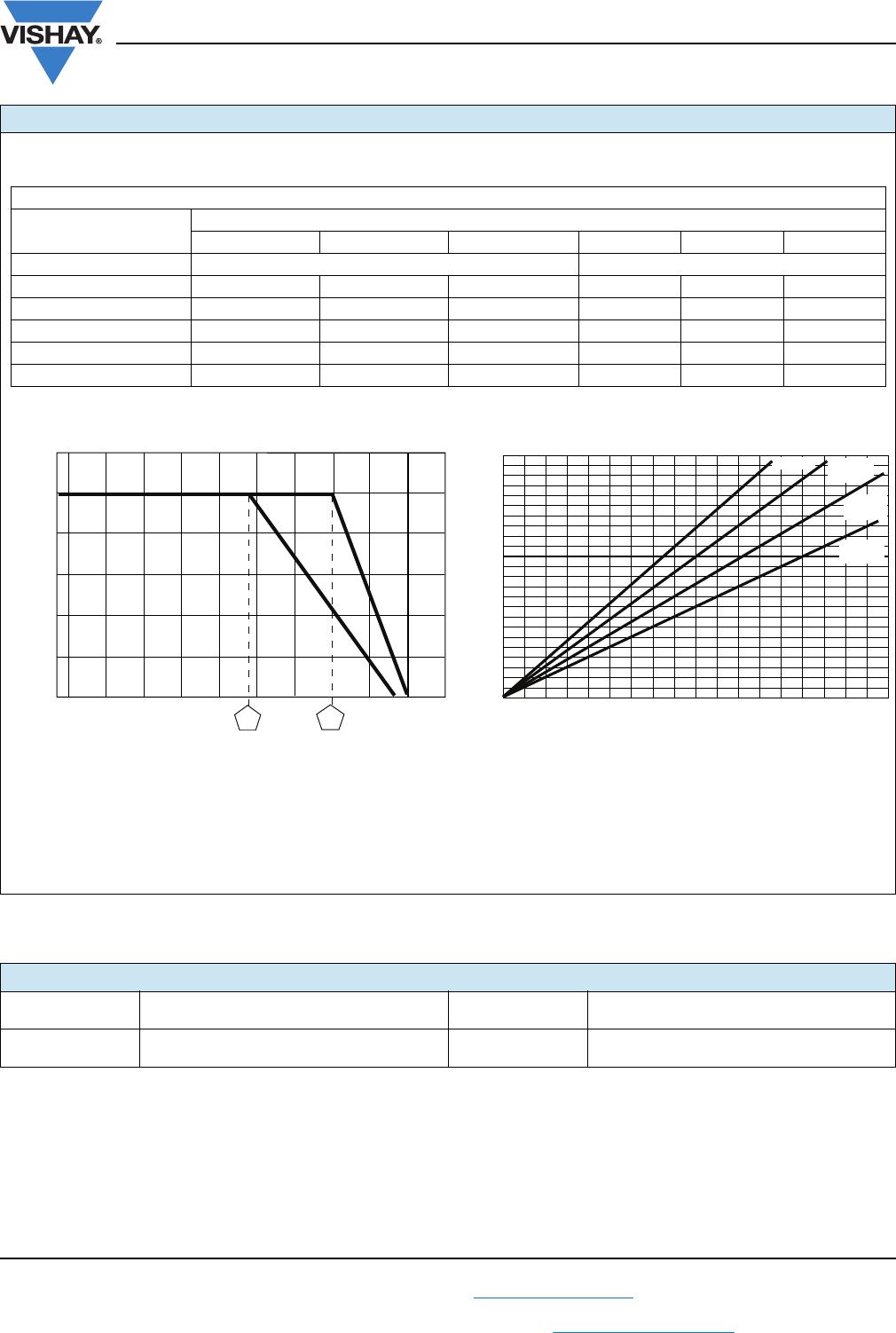
MAXIMUM COMMERCIAL POWER RATING
WATTAGE
(2)
MODEL
CMF50 CMF55 CMF60 CMF65 CMF70 CMF07 CMF20
At + 70 °C 0.25 W 0.5 W 1 W 1 W 1 W 0.5 W 1 W
At + 125 °C 0.125 W 0.25 W 0.5 W 0.75 W 0.75 W - -
GLOBAL PART NUMBER INFORMATION
P x R
GLOBAL MODEL RESISTANCE VALUE TOLERANCE PACKAGING
CODE
(See Standard R = Ω B = ± 0.1 % E = 25 ppm
EK = Lead (Pb)-free, bulk
EA = Lead (Pb)-free, T/R (full)
EB = Lead (Pb)-free,
T/R (1000 pieces)
Electrical K = kΩ C = ± 0.25 % H = 50 ppm
Specifications M = MΩ D = ± 0.5 % K = 100 ppm
table) R10000 = 0.1 Ω F = ± 1 % L = 150 ppm
680K00 = 680 kΩ G = ± 2 % N = 200 ppm
1M0000 = 1.0 MΩ J = ± 5 %
New Global Part Numbering: CMF55301R00FKRE (preferred part numbering format)
CMF55301R00FKRE
Historical Part Number example: CMF-553010FT-1 (will continue to be accepted)
63R1-TF010355-FMC
HISTORICAL MODEL RESISTANCE VALUE TOLERANCE CODE TEMP. COEFFICIENT PACKAGING
Blank = Standard
(Dash Number)
(Up to 3 digits)
From
1 to 999
as applicable
70 = Color banded,
5 bands ( 1 %)
80 = Color banded,
4 bands ( 2 %)
88 = Hot solder dip
SPECIAL
TEMPERATURE
COEFFICIENT
(3)
BF = Tin/lead, bulk
RE = Tin/lead, T/R (full)
R6 = Tin/lead, T/R (1000 pieces)
CMF Industrial
www.vishay.com
Vishay Dale
Revision: 19-Nov-12
2
Document Number: 31018
For technical questions, contact: ff2aresistors@vishay.com
THIS DOCUMENT IS SUBJECT TO CHANGE WITHOUT NOTICE. THE PRODUCTS DESCRIBED HEREIN AND THIS DOCUMENT
ARE SUBJECT TO SPECIFIC DISCLAIMERS, SET FORTH AT www.vishay.com/doc?91000
Notes
(1)
Lead length for product in bulk pack. For product supplied in tape and reel, the actual lead length would be based on the body size, tape
spacing and lead trim.
(2)
Available with 0.032" (0.813 mm) lead [CMF60..95]
(3)
0.290" (7.37 mm) for ± 0.25 % and ± 0.1 % resistance tolerances and values > 1 M
(4)
0.260" ± 0.020" (6.60 mm ± 0.51 mm) for values > 5 M
DIMENSIONS in inches (millimeters)
GLOBAL MODEL A B
C
(Max.)
D
CMF50
0.150 ± 0.020
(3.81 ± 0.51)
0.065 ± 0.015
(1.65 ± 0.38)
0.187 (4.75)
0.016 ± 0.002
(0.41 ± 0.05)
CMF55
0.240 ± 0.020
(4)
(6.10 ± 0.51)
0.090 ± 0.008
(2.29 ± 0.20)
0.278 (7.06)
(3)
0.025 ± 0.002
(0.64 ± 0.05)
CMF60
0.344 ± 0.031
(8.74 ± 0.79)
0.145 ± 0.015
(3.68 ± 0.38)
0.425 (10.80)
0.025 ± 0.002
(2)
(0.64 ± 0.05)
CMF65
0.562 ± 0.031
(14.27 ± 0.79)
0.180 ± 0.015
(4.57 ± 0.38)
0.687 (17.45)
0.025 ± 0.002
(0.64 ± 0.05)
CMF70
0.562 ± 0.031
(14.27 ± 0.79)
0.180 ± 0.015
(4.57 ± 0.38)
0.687 (17.45)
0.032 ± 0.002
(0.81 ± 0.05)
CMF07
0.240 ± 0.020
(6.10 ± 0.51)
0.090 ± 0.008
(2.29 ± 0.20)
0.278 (7.06)
0.025 ± 0.002
(0.64 ± 0.05)
CMF20
0.375 ± 0.040
(9.53 ± 1.02)
0.145 ± 0.015
(3.68 ± 0.38)
0.425 (10.80)
0.032 ± 0.002
(0.81 ± 0.05)
TECHNICAL SPECIFICATIONS
PARAMETER UNIT CMF50 CMF55 CMF07 CMF60 CMF20 CMF65 CMF70
Maximum Working Voltage V200 250 250 500 500 500 500
Insulation Voltage (1 Min) V
eff
> 500
Voltage Coefficient (Max.) ppm/V ± 5 (measured between 10 % and full rated voltage)
Dielectric Strength V
AC
450 450 450 750 750 900 900
Insulation Resistance 10
11
Operating Temperature Range °C - 55 to + 175
Terminal Strength (Pull Test) lb 2 2 5 2 5 2 5
Noise dB
0.10 μV/V over a decade of frequency, with low and intermediate resistance values typically
below 0.05 μV/V
Weight (Max.) g 0.12 0.20 0.20 0.50 0.60 1.00 1.10
TEMPERATURE COEFFICIENT CODES
GLOBAL TC CODE HISTORICAL TC CODE TEMPERATURE COEFFICIENT
E T-9 25 ppm/°C
H T-2 50 ppm/°C
K T-1 100 ppm/°C
L T-0 150 ppm/°C
N T-00 200 ppm/°C
B
D
C
(Max.)
1.500 ± 0.125
(1)
[38.10 ± 3.18]
A
CMF Industrial
www.vishay.com
Vishay Dale
Revision: 19-Nov-12
3
Document Number: 31018
For technical questions, contact: ff2aresistors@vishay.com
THIS DOCUMENT IS SUBJECT TO CHANGE WITHOUT NOTICE. THE PRODUCTS DESCRIBED HEREIN AND THIS DOCUMENT
ARE SUBJECT TO SPECIFIC DISCLAIMERS, SET FORTH AT www.vishay.com/doc?91000
LOAD LIFE SHIFT DUE TO POWER AND DERATING (AT 70 °C AND AT + 125 °C)
The power rating for the CMF parts is tied to the derating temperature, the heat rise of the parts, and the R for the load life performance.
When the tables/graphs below are used together they show that when the parts are run at their higher power ratings, the parts will run hotter,
which has the potential of causing the resistance of the parts to shift more over the life of the part.
LOAD LIFE SHIFT VS. POWER RATING
LOAD LIFE
MAXIMUM R (TYPICAL TEST LOTS)
± 0.15 % ± 0.5 % ± 1.0 % ± 0.15 % ± 0.5 % ± 1.0 %
MODEL POWER RATING AT + 70 °C POWER RATING AT + 125 °C
CMF50 1/20 W and 1/10 W 1/8 W 1/4 W 1/20 W 1/10 W 1/8 W
CMF55, CMF07 1/10 W and 1/8 W 1/4 W 1/2 W 1/10 W 1/8 W 1/4 W
CMF60, CMF20 1/8 W and 1/4 W 1/2 W 3/4 W and 1 W 1/8 W 1/4 W 1/2 W
CMF65 1/4 W and 1/2 W 3/4 W 1 W 1/4 W 1/2 W 3/4 W
CMF70 1/4 W and 1/2 W 3/4 W 1 W 1/4 W 1/2 W 3/4 W
CMF resistors have an operating temperature range of - 55 °C to +
175 °C. They must be derated at high ambient temperatures
according to the derating curve.
Example:
When a CMF55 part is run at 1/8 W in a 70 °C ambient environment, the resistor will generate enough heat that the surface temperature of
the part will reach about 19 °C over the ambient temperature, and over the life of the part this could cause the resistance value to shift up to
± 0.15 %.
If the same resistor was instead run at 1/4 W in a 70 °C environment, the element will heat up to about 30 °C over ambient, and over the life
of the part the resistance value could shift roughly ± 0.5 %.
And if the resistor was run at it maximum power rating of 1/2 W in a 70 °C environment, it will heat up to about 58 °C over ambient, and you
could see the resistance value shift roughly ± 1 % over the life of the part.
AMBIENT TEMPERATURE IN °C
DERATING
120
100
80
60
40
20
0
% NI REWOP DETAR
- 55
- 50
- 25
0
25 70 75 100 125
150
165
175
50 200
APPLIED POWER IN W
THERMAL RESISTANCE
120
100
80
60
40
20
0
HEAT RISE (°C ABOVE AMBIENT)
0 0.125 0.25 0.375 0.5 0.75 0.875
1
1.1250.625
CMF50
CMF55,
CMF07
CMF60,
CMF20
CMF65,
CMF70
MATERIAL SPECIFICATIONS
Element: Vacuum-deposited nickel-chrome alloy Coating:
Flame retardant epoxy, formulated for superior
moisture protection
Core: Fire-cleaned high purity ceramic Solderability:
Continuous satisfactory coverage when tested
in accordance with MIL-R-10509

CMF65300R00FKR6

Mfr. #:
Manufacturer:
Vishay / Dale
Description:
RES 300 OHM 1.5W 1% AXIAL
Lifecycle:
New from this manufacturer.
Delivery:
DHL FedEx Ups TNT EMS
Payment:
T/T Paypal Visa MoneyGram Western Union