T83
www.vishay.com
Vishay Sprague
Revision: 08-Jan-13
3
Document Number: 40077
For technical questions, contact: tantalum@vishay.com
THIS DOCUMENT IS SUBJECT TO CHANGE WITHOUT NOTICE. THE PRODUCTS DESCRIBED HEREIN AND THIS DOCUMENT
ARE SUBJECT TO SPECIFIC DISCLAIMERS, SET FORTH AT www.vishay.com/doc?91000
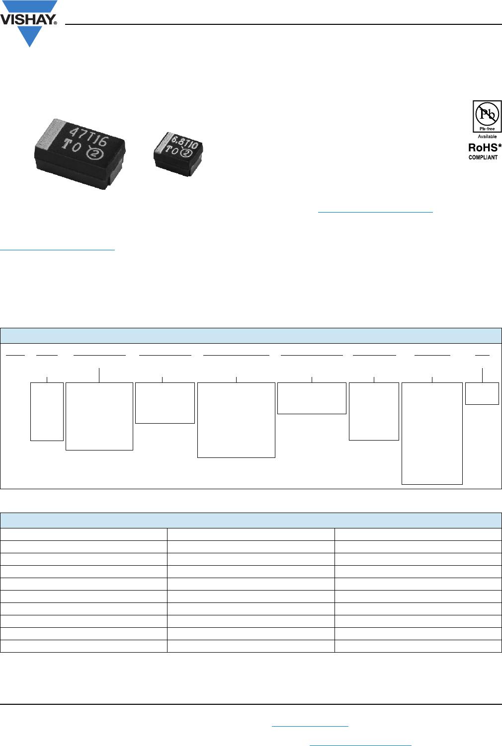
MARKING
“A” CASE VOLTAGE CODE
VOLTS CODE
4.0 G
6.3 J
10 A
16 C
20 D
25 E
35 V
50 T
Marking
Capacitor marking includes an anode (+) polarity band, capacitance in microfarads and the voltage rating. “A” case capacitors use a letter
code for the voltage and EIA capacitance code.
The Vishay Sprague
®
trademark is included if space permits. Capacitors rated at 6.3 V are marked 6 V.
A manufacturing date code is marked on all capacitors.
Call the factory for further explanation.
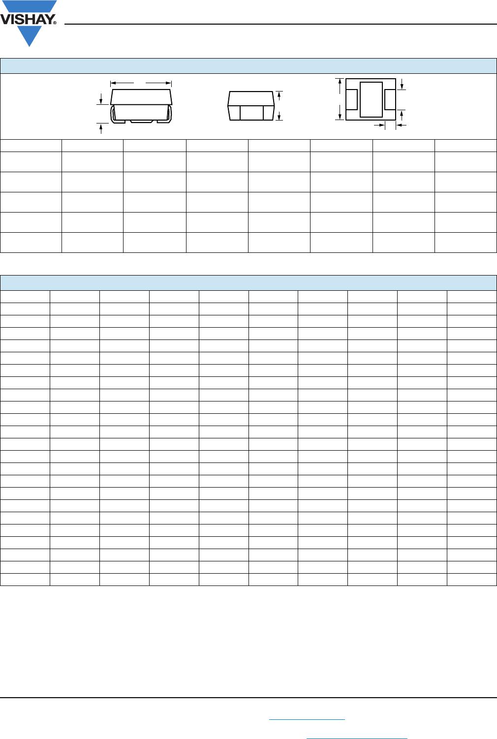
STANDARD RATINGS
CAPACITANCE
(μF)
CASE CODE PART NUMBER
MAX. DCL
AT + 25 °C
(μA)
MAX. DF
AT + 25 °C
120 Hz
(%)
STD. (S)
MAX. ESR
AT + 25 °C
100 kHz
()
LOW (L)
MAX. ESR
AT + 25 °C
100 kHz
()
AVAILABLE
RELIABILITY
LEVELS
4 V
DC
AT + 85 °C; 2.7 V
DC
AT + 125 °C
2.2 A T83A225(1)004(2)(6)(4)(5) 0.50 6 7.600 6.000 A, B, C, S, Z
3.3 A T83A335(1)004(2)(3)(4)(5) 0.50 6 7.600 4.000 A, B, S, Z
4.7 A T83A475(1)004(2)(6)(4)(5) 0.50 6 6.300 3.500 A, B, C, S, Z
6.8 B T83B685(1)004(2)(6)(4)(5) 0.50 6 4.500 2.000 A, B, C, S, Z
10 B T83B106(1)004(2)(6)(4)(5) 0.50 6 3.500 1.200 A, B, C, S, Z
15 B T83B156(1)004(2)(6)(4)(5) 0.60 6 2.900 1.200 A, B, C, S, Z
33 A T83A336(1)004(2)(3)(4)(5) 1.3 6 2.900 1.500 A, B, S, Z
33 C T83C336(1)004(2)(6)(4)(5) 1.3 6 1.800 0.500 A, B, C, S, Z
47 B T83B476(1)004(2)(3)(4)(5) 1.9 6 2.500 0.600 A, B, S, Z
47 C T83C476(1)004(2)(3)(4)(5) 1.9 6 1.800 0.400 A, B, S, Z
68 D T83D686(1)004(2)(6)(4)(5) 2.7 6 0.800 0.175 A, B, C, S, Z
100 B T83B107(1)004(2)(3)(4)(5) 4.0 6 1.800 0.450 A, B, S, Z
100 D T83D107(1)004(2)(6)(4)(5) 4.0 6 0.700 0.175 A, B, C, S, Z
150 D T83D157(1)004(2)(3)(4)(5) 6.0 8 0.600 0.150 A, B, S, Z
330 E T83E337(1)004(2)(3)(4)(5) 13.2 8 0.500 0.100 A, B, S, Z
6 V
DC
AT + 85 °C; 4 V
DC
AT + 125 °C
1.5 A T83A155(1)6R3(2)(6)(4)(5) 0.50 6 8.000 6.000 A, B, C, S, Z
2.2 A T83A225(1)6R3(2)(6)(4)(5) 0.50 6 7.600 6.000 A, B, C, S, Z
3.3 A T83A335(1)6R3(2)(6)(4)(5) 0.50 6 6.300 5.000 A, B, C, S, Z
4.7 A T83A475(1)6R3(2)(3)(4)(5) 0.50 6 5.500 3.500 A, B, S, Z
4.7 B T83B475(1)6R3(2)(6)(4)(5) 0.50 6 3.400 1.800 A, B, C, S, Z
6.8 B T83B685(1)6R3(2)(6)(4)(5) 0.50 6 3.400 1.200 A, B, C, S, Z
Note
• Part number definitions:
(1) Capacitance tolerance: K, M
(2) Termination and packaging: C, E, K, H, L, M, U, R, N
(3) Reliability level: A, B, S, Z
(4) Surge current: A, B, C, Z, S
(5) ESR: L, S
(6) Reliability level: A, B, C, S, Z
(7) Reliability level: A, S, Z
Capacitance Code, pF
Indicates Hi-Rel COTS
Polarity Band (+)
Voltage
Code
V
104T
A Case
Date Code
Vishay
Sprague Logo
Indicates Hi-Rel COTS
Voltage
Capacitance μF
Polarity
Band (+)
22 T10
XX
2
B, C, D, E Cases