3
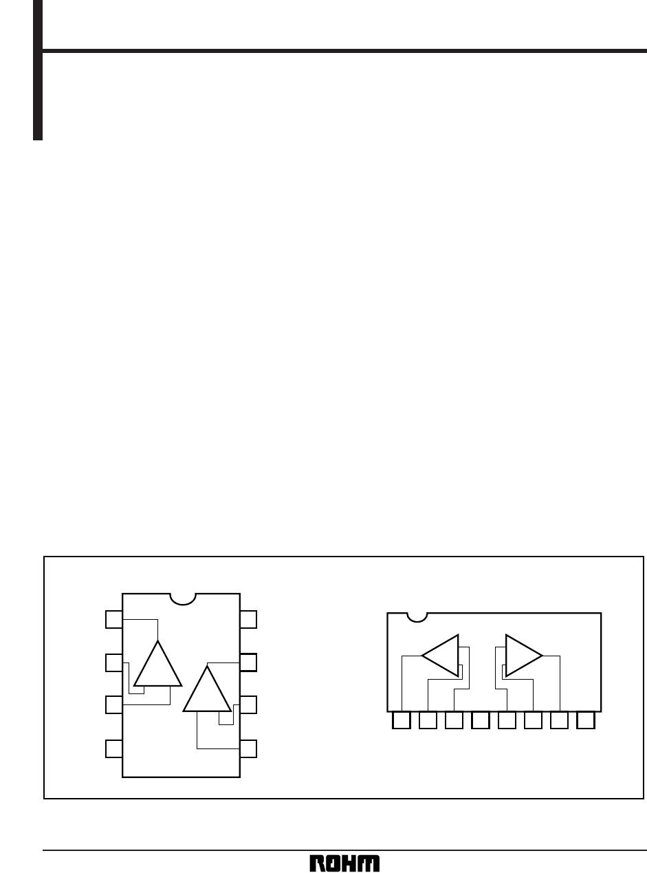
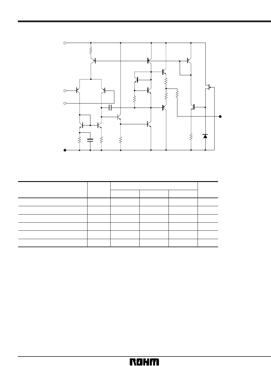
Standard ICs BA4558 / BA4558F / BA4558N
•
Electrical characteristics (unless otherwise noted, Ta = 25°C, VCC = + 15V, VEE = – 15V)
Parameter Symbol Typ. Max. Unit
Input offset voltage V
IO — 0.5 6.0 mV RS ⬉ 10kΩ
Input offset current I
IO — 5 200 nA
Input bias current I
B — 60 500 nA
High-amplitude voltage gain A
V 86 100 — dB
Common-mode input voltage V
ICM ± 12 ± 14 — V
Maximum output voltage V
OH ± 12 ± 14 — V RL ⭌ 10kΩ
Minimum output voltage V
OL ± 10 ± 13 — V RL ⭌ 2kΩ
Common-mode rejection ratio CMRR 70 90 — dB R
S ⬉ 10kΩ
Power supply voltage rejection ratio PSRR — 30 150 µV / V R
S ⬉ 10kΩ
Slew rate S.R. — 1.0 — V /
µs
Channel separation CS — 105 — dB f = 1kHz
ConditionsMin.
R
L ⭌ 2kΩ, VO = ± 10V
A
V = 1, RL ⭌ 2kΩ
•
Electrical characteristic curves
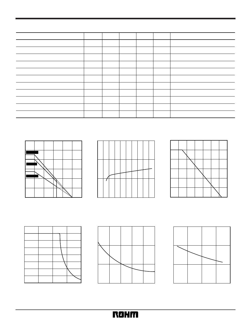
Fig.1 Power dissipation vs. ambient
temperature
AMBIENT TEMPERATURE: Ta (°C)
POWER DISSIPATION: Pd (mW)
1200
1000
800
600
400
200
0
0 25 50 75 85 100 125 150
BA4558N
BA4558F
BA4558
4
5
3
2
0 ± 10 ± 20
POWER SUPPLY VOLTAGE: V
±
(V)
QUIESCENT CURRENT: IQ (mA)
Fig.2 Quiescent current vs. power
supply voltage
1M 10M
120
100
80
60
40
20
0
1 10 100 1k 10k 100k
FREQUENCY: f (Hz)
OPEN LOOP GAIN: AV (dB)
Fig.3 Open loop voltage gain vs.
frequency
32
28
24
20
16
12
8
4
0
100 1k 10k 100k 1M
FREQUENCY: f (Hz)
MAXIMUM OUTPUT VOLTAGE: VOM (V)
Fig.4 Maximum output voltage vs.
frequency
100
80
60
40
– 200 20406080
AMBIENT TEMPERATURE: Ta (°C)
INPUT BIAS CURRENT: IB (mA)
Fig.5 Input bias current vs. ambient
temperature
100
75
50
25
010203040
POWER SUPPLY VOLTAGE: V
+
(V)
INPUT BIAS CURRENT: IB (nA)
Fig.6 Input bias current vs. power
supply voltage