– 3 –
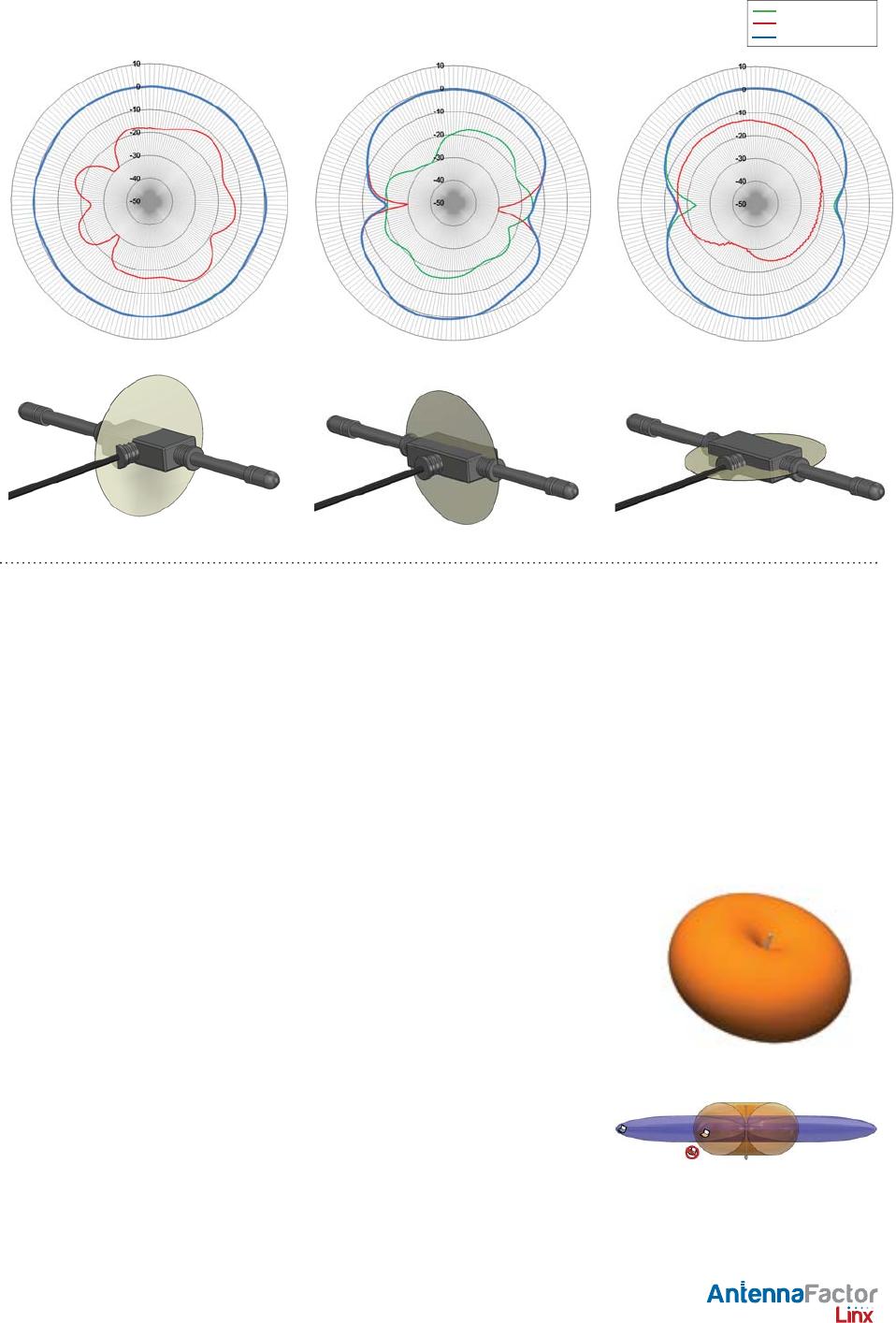
About Gain Plots
The true measure of the effectiveness of an antenna in any given applica-
tion is determined by the gain and radiation pattern measurement. For
antennas gain is typically measured relative to a perfect (isotropic) radia-
tor having the same source power as the antenna under test, the units of
gain in this case will be decibels isotropic (dBi). The radiation pattern is a
graphical representation of signal strength measured at fi xed distance from
the antenna.
Gain when applied to antennas is a measure of how the antenna radiates
and focuses the energy received into free space. Much like a fl ashlight
focuses light from a bulb into a specifi c direction, antennas can focus RF
energy into specifi c directions. Gain in this sense refers to an increase in
energy in one direction over others.
It should also be understood that gain is not “free”, gain above 0dBi in one
direction means that there must be less gain in another direction. Pictori-
ally this can be pictured as shown in the fi gures to the right. The orange
pattern represents the radiation pattern for a perfect dipole antenna,
which is shaped like a donut. The pattern for an omnidirectional antenna
with gain is shown in blue. The gain antenna is able to work with a device
located further from the center along the axis of the pattern, but not with
devices closer to the center when they are off the axis – the donut has
been squished.
Gain is also related to the overall physical size of the antenna, as well as
surrounding materials. As the geometry of the antenna is reduced below
the effective wavelength (considered an electrically small antenna) the gain
will decrease. As well, the relative distance between an electrically small
antenna and its associated ground will impact antenna gain.
159 Ort Lane, Merlin, OR, US 97532
Phone: +1 541 471 6256
Fax: +1 541 471 6251
www.linxtechnologies.com
by
Gain Plots
E / Vertical Gain
H / Horizontal Gain
Total Gain
XZ-Plane Gain
YZ-Plane Gain XY-Plane Gain
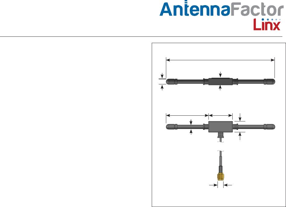
Data Sheet ANT-433-MHW-xxx-x