Y17451K00000T9R

IM
PR
OVED
PR
OD
U
C
T
Ultra High Precision Z-Foil Molded Surface Mount Resistor with
TCR down to ± 0.05 ppm/°C
, PCR of ± 5 ppm at Rated Power,
Flexible Terminations, and Load Life Stability of ± 0.005 %
(50 ppm)
SMR1DZ/SMR3DZ (Z-Foil)
Vishay Foil Resistors
Document Number: 63118 For any questions, contact: foil@vishaypg.com www.foilresistors.com
Revision: 25-Mar-10 1
Any value at any tolerance available within resistance range
INTRODUCTION
The SMRxDZ is an ultra high precision molded surface
mountable resistor offering all the elements of precision;
including low TCR, tight tolerance, long term stability, low
noise, low thermal EMF, and non-measurable voltage
coefficient. One of the important parameters influencing
stability is the Temperature Coefficient of Resistance (TCR).
Although the TCR of foil resistors is considered extremely
low, this characteristic has been further refined over the
years. The SMRxDZ utilizes ultra high precision Bulk Metal
®
Z-Foil.
The Z-Foil technology provides a significant reduction of
the resistive element’s sensitivity to ambient temperature
variations (TCR) and to self heating when power is applied
(power coefficient).
Voltage division with tight tracking < 2 ppm/°C can be
achieved with 2 randomly selected units even with a large
ratio between the two values.
Our Application Engineering Department is available to
advise and make recommendations. For non-standard
technical requirements and special applications, please
contact us.
Note
1. Tighter performances are available
FEATURES
Temperature Coefficient of Resistance (TCR):
± 0.05 ppm/°C typical (0 °C to + 60 °C)
± 0.2 ppm°C typical (- 55 °C to + 125 °C,
+ 25 °C Ref.)
Tolerance: to ± 0.01 %
Power Coefficient of Resistance (PCR)
R due to self heating”: 5 ppm at Rated Power
Flexible Terminations ensure minimal stress transference
from the PCB due to a difference in Thermal Coefficient of
Expansions (TCE)
Electrostatic Discharge (ESD) above 25 000 Volts
Load Life Stability: ± 0.005 % (70 °C, 2000 hours at Rated
Power)
Resistance Range: 5 to 80 k (for higher and lower
values, please contact us)
Power Rating: to 600 mW at 70 °C
Non Inductive, Non Capacitive Design
Current Noise: - 40 dB
Voltage Coefficient: < 0.1 ppm/V
Non Inductive: < 0.08
Non Hot Spot Design
Terminal Finishes available: Lead (Pb)-free
Tin/Lead Alloy
Matched sets with TCR tracking are available upon request
For higher Performances please contact us
Any Value available within Resistance Range (e.g. 1K234)
Prototype Samples available from 48 hours. For more
Information, please contact foil@vishaypg.com
APPLICATIONS
Precision Amplifiers
High Precision Instrumentation
Medical
Automatic Test Equipment (ATE)
Industrial
Audio (High End Stereo
Equipment)
EB Application
Military, Airborne and Space
Pulse Application
Measurement Instrumentation
* Pb containing terminations are not RoHS compliant, exemptions may apply
TABLE 1 - TOLERANCE AND TCR VERSUS
RESISTANCE VALUE
(- 55 °C to + 125 °C, + 25 °C Ref.)
VALUE
STANDARD
TOLERANCE
1)
TYPICAL TCR AND
MAX. SPREAD
1)
(ppm/°C)
50 to 80 k ± 0.01 % ± 0.2 ± 1.8
20 to < 50 ± 0.02 % ± 0.2 ± 2.8
10 to < 20 ± 0.05 % ± 0.2 ± 4.8
5 to < 10 ± 0.1 % ± 0.2 ± 6.8
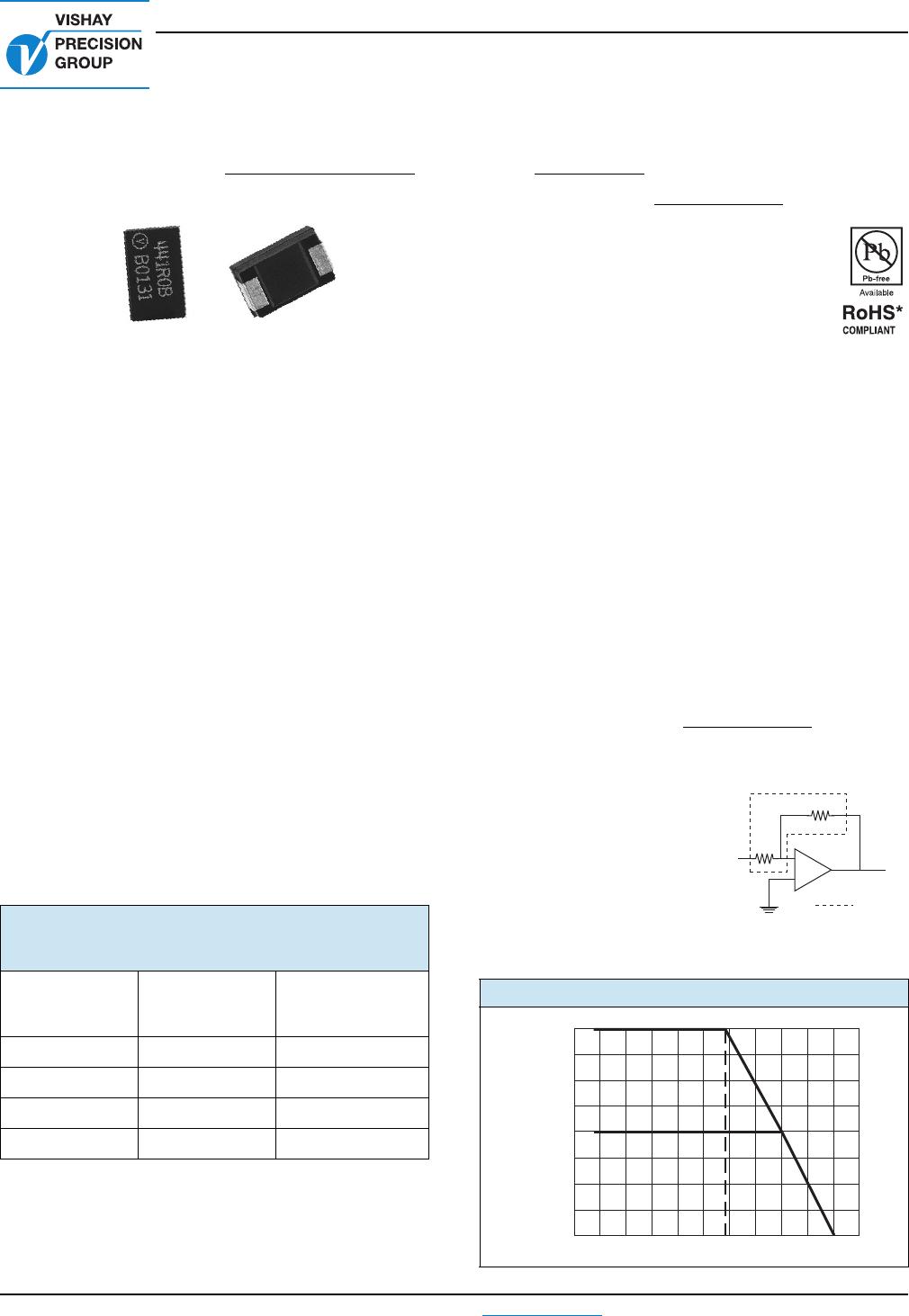
FIGURE 1 - POWER DERATING CURVE
R
1
R
2
V
in
V
out
-
+
SMRxDZ
200
175
150
125
100
75
50
25
0
- 75 - 25 + 25 + 75 + 125 + 175
Ambient Temperature (°C)
Percent of Rated Power (%)
- 55 °C + 70 °C
SMR1DZ/SMR3DZ (Z-Foil)
Vishay Foil Resistors
www.foilresistors.com For any questions, contact: foil@vishaypg.com Document Number: 63118
2 Revision: 25-Mar-10
I
MPRO
VE
D PR
OD
U
C
T
Note
1. As shown + 0.01 to allow for measurement error at low values
TABLE 2 - PERFORMANCE SPECIFICATIONS
TEST CONDITIONS
MAXIMUM LIMIT
1)
SMR1DZ SMR3DZ SMR1DZ SMR3DZ
Resistance Range 5 to 33 k 5 to 80 k
Rated Power
5 to 10 k
0.250 W at 70 °C
0.125 W at 125 °C
10 k to 33 k
0.160 W at 70 °C
0.08 W at 125 °C
5 to 30 k
0.6 W at 70 °C
0.3 W at 125 °C
30 k to 80 k
0.4 W at 70 °C
0.2 W at 125 °C
See figure 1
Maximum Working Voltage 73 V 180 V
Maximum Operating
Temperature
+ 175 °C (see Figure 1)
Working Temperature Range - 55 °C to + 125 °C (MIL range)
Thermal Shock - 65 °C to + 175 °C; 30 minutes; 5 cycles ± 0.01 % (100 ppm)
Short Time Overload 6.25 x Rated Power; 5 seconds ± 0.01 % (100 ppm)
Low Temperature Operation - 65 °C, 24 hours (no load): 45 minutes at Rated Power ± 0.01 % (100 ppm)
Dielectric Withstanding
Voltage
Atmospheric Pressure; AC 200 V; 1 minute ± 0.01 % (100 ppm)
Insulation Resistance (M) DC 100 V; 1 minute over 10 000
Resistance to
Soldering Heat (%)
260 °C; 10 seconds ± 0.02 %, ± 0.01 % typical
Moisture Resistance + 65 °C to - 10 °C; 90 % to 98 % RH; Rated Power; 240 hours ± 0.02 % (200 ppm)
Shock 100 G; Sawtooth ± 0.01 % (100 ppm)
Vibration, High Frequency 10 ~ 2000 ~ 10 Hz; 20 G; X, Y, Z each 2.5 hours ± 0.01 % (100 ppm)
Load Life Stability (2000 h)
0.04 W at + 70 °C
0.25 W at + 70 °C
0.125 W at + 125 °C
0.1 W at + 70 °C
0.6 W at + 70 °C
0.3 W at + 125 °C
Ty pi ca l
0.005 %
0.02 %
0.02 %
Typical
0.005 %
0.015 %
0.015 %
High Temperature Exposure 175 °C; no Load 2000 hours ± 0.05 % (500 ppm)
Weight 0.1143 g 0.244 g
Packaging Bulk (loose) or Tape and Reel, per EIA-481-1
SMR1DZ/SMR3DZ (Z-Foil)
Vishay Foil Resistors
Document Number: 63118 For any questions, contact: foil@vishaypg.com www.foilresistors.com
Revision: 25-Mar-10 3
IM
PR
OVED
PR
OD
U
C
T
Notes
For more details, see table 1
The TCR values for < 80 are influenced by the termination
composition and the result in deviation from this curve
FIGURE 2 - DIMENSIONS in inches (millimeters)
MODEL L W H P TW TH (minimum)
SMR1DZ
0.236 ± 0.012
(5.99 ± 0.30)
0.126 ± 0.012
(3.20 ± 0.30)
0.098 ± 0.012
(2.49 ± 0.30)
0.051 ± 0.012
(1.30 ± 0.30)
0.087 ± 0.004
(2.21 ± 0.10)
0.039
(0.99)
SMR3DZ
0.287 ± 0.012
(7.29 ± 0.30)
0.170 ± 0.012
(4.32 ± 0.30)
0.110 ± 0.012
(2.79 ± 0.30)
0.051 ± 0.012
(1.30 ± 0.30)
0.095 ± 0.004
(2.41 ± 0.10)
0.039
(0.99)
TH Minimum
Side View
Stand Off
W
Bottom View
L
PP
End View
H
TW
Top View
100R0T
(DATE CODE) -
V
z
TOLERANCE
Z-FOIL
INDICATOR
LEAD (Pb)-FREE INDICATOR
VALUE (5 DIGITS)
FIGURE 3 - RECOMMENDED MOUNTING PAD GEOMETRIES in inches (millimeters)
MODEL METHOD
A
MIN.
B
REF
C
REF
D
± 0.04 (± 1.02)
E
REF
SMR1DZ Reflow
0.110
(2.79)
0.106
(2.69)
0.124
(3.15)
0.337
(8.55)
0.050
(1.27)
SMR3DZ Reflow
0.118
(3.00)
0.106
(2.69)
0.175
(4.45)
0.388
(9.86)
0.050
(1.27)
Per IPC-SM-782 Rev A
E
A
C
B
D
Reflow Solder Pads
FIGURE 4 - TRIMMING TO VALUES
(conceptual illustration)
Mutual Inductance
Reduction due
to Change in
Current Direction
Current Path
Before Trimming
Trimming Process
Removes this Material
from Shorting Strip Area
Changing Current Path
and Increasing
Resistance
NOTE: Foil shown in black, etched spaces in white
Current Path
After Trimming
Interloop Capacitance
Reduction in Series
FIGURE 5 - TYPICAL TCR CURVE Z-FOIL
+ 500
+ 200
+ 100
0
- 100
- 200
- 300
- 500
- 55 - 25 + 25 + 60 + 75 + 100 + 125
Ambient Temperature (°C)
ΔR
R
(ppm)
0
0.05 ppm/°C
- 0.1 ppm/°C 0.1 ppm/°C
0.14 ppm/°C
0.2 ppm/°C
- 0.16 ppm/°C
- 400
+ 300
+ 400

Y17451K00000T9R

Mfr. #:
Manufacturer:
Vishay Precision Group
Description:
Metal Foil Resistors - SMD 1Kohms tcr0.2 0.01% .6w
Lifecycle:
New from this manufacturer.
Delivery:
DHL FedEx Ups TNT EMS
Payment:
T/T Paypal Visa MoneyGram Western Union