Design Guide & Applications Manual
F
or Maxi, Mini, Micro Family DC-DC Converters and Configurable Power Supplies
Maxi, Mini, Micro Design Guide Rev 4.4 vicorpower.com
Page 78 of 88
Apps. Eng. 800-927-9474 800 735.6200
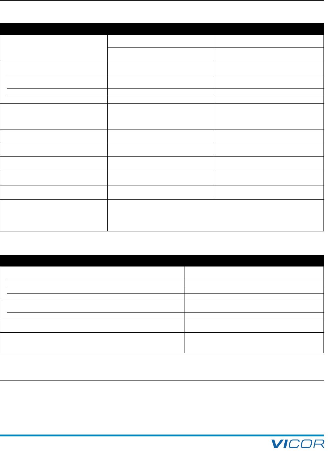
16. Through-hole Socket Mount System (InMate)
Table 16–2 — InMate specifications and materials
Table 16–3 — Material properties of InMate components
Parameter Specification Value Reference
Compatibility F = short Au plated Short RoHS pins
Module pin styles
S = short Au plated Short ModuMate pins
G = long Au plated Long RoHS pins
N = long Au plated Long ModuMate pins
Mechanical
Contact normal force 100 grams EOL min. GR-1217-CORE, R5-23
Number of mating cycles 5 max.
(Note4)
Exception to GR-1217-CORE
which specifies 25 mating cycle
Module engagement force 32 lbs per connector max. GR-1217-CORE, R5-31,32
Module disengagement force 32 lbs per connector max. GR-1217-CORE, R5-31,32
Electrical
Current rating for output pin sockets
50 A Maxi
(Note1)
/ 50 A Mini / 25 A Micro Gold plating standards, and
(Based on 248°F (120°C) max socket temp. & accepted industry standards
86°F (30°C) max temperature rise of contact) such as IICIT, EIA, Bellcore guidelines
Low level contact resistance
0.080" (2,03 mm) dia socket (LLCR) 400 µΩ max. GR-1217-CORE, 6.2.1
Low level contact resistance
0.150" (3,81 mm) dia socket (LLCR) 300 µΩ max. GR-1217-CORE, 6.2.1
Low level contact resistance
0.180" (4,57 mm) dia sockets (LLCR) 200 µΩ max. GR-1217-CORE, 6.2.1
Thermal
Max continuous use
Max socket temperature
248°F (120°C) max.
temperature for gold plating
Temperature rise
86°F (30°C) max.
GR-1217-CORE
(Note3)
EIA-364-70A
(Note2)
Environmental InMate products are tested in random vibration environments to best simulate the broad spectrum
Shock and vibration of frequencies and amplitudes that may be encountered in typical applications. Actual system
resonant frequencies will depend on PCB construction and mounting details.
For critical, or unusual, shock and vibration environments, the performance of the system should
be independently verified.
Materials Ratings
Headers
Material: Ryton
TM
R–7 PPS, 65% glass fiber and mineral filled compound Poly-Phenylene Sulfide
Flammability UL94 V-0/5VA
Thermal stability (short term) 500°F (260°C)
Thermal stability (long term) 392°F (200°C)
Solder Cap
Material
305 stainless steel
Plating Clear passivate to repel solder
Sockets Brush Wellman Alloy #25
Material C17200 deep draw quality or equiv. 0.010" thick
Plating
Woods nickel strike followed by 50 µ in. min. low stress
sulfamate-based electrolytic nickel, followed by
20 µ in min hard gold followed by 10 µ in. min. soft gold
(Note1)
For 80 A operation with Maxi, contact Applications Engineering.
(Note2)
GR-1217-CORE issue 1, November 1995 Generic requirements for
separable electrical connectors used in telecommunications
hardware. A module of NEBSFR, FR-2063
(Note3)
ANSI/EIA-364 American National Standards Institute / Electronic
Industries Association (Electronic Components, Assemblies &
Materials Association)
(Note4)
The module and socket must be replaced after 5 mating cycles.
(1)
For 80 A operation with Maxi, contact Applications Engineering.

