6
Absolute Maximum Ratings at T
A
= 25˚C
Parameter Red and Amber
DC Forward Current
[1]
50 mA
Peak Pulsed Forward Current
[2]
100 mA
Average Forward Current 30 mA
Reverse Voltage (I
R
= 100 µA) 5 V
Power Dissipation 120 mW
LED Junction Temperature 130°C
Operating Temperature Range –40°C to +100°C
Storage Temperature Range –40°C to +100°C
Notes:
1. Derate linearly as shown in gure 4.
2. Duty Factor 30%, Frequency 1kHz.
Electrical/Optical Characteristics at T
A
= 25°C
Parameter Symbol Min. Typ. Max. Units Test Conditions
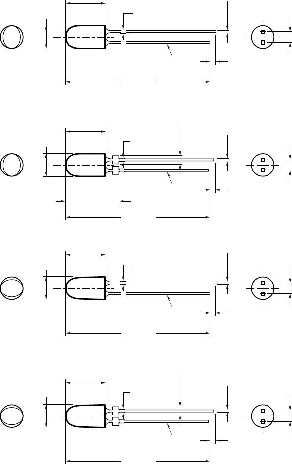
Typical Viewing Angle
Major 2q
1/2
70 deg
Minor 35
Forward Voltage V
F
V I
F
= 20 mA
Red (l
d
= 626 nm) 2.0 2.4
Red (l
d
= 630 nm)
Option xx0xx 2.2 2.4
Option xxTxx 2.3 2.6
Amber (l
d
= 590 nm) 2.0 2.4
Amber (l
d
= 592 nm)
Option xx0xx 2.2 2.4
Option xxRxx, xxSxx 2.3 2.6
Reverse Voltage
Amber, Red V
R
5 20 V I
R
= 100 µA
Peak Wavelength Peak of Wavelength of
Amber (l
d
= 592 nm) l
peak
594 nm Spectral Distribution
Red (l
d
= 630 nm) 639 at I
F
= 20 mA
Spectral Halfwidth Wavelength Width at
Amber (l
d
= 592 nm) ∆l
1/2
17 nm Spectral Distribution 1/2
Red (l
d
= 630 nm) 17 Power Point at I
F
= 20 mA
Capacitance V
F
= 0, F = 1 MHz
Amber, Red C 40 pF
Luminous Ecacy Emitted Luminous
Amber (l
d
= 592 nm) h
v
500 lm/W Power/Emitted Radiant
Red (l
d
= 630 nm) 155 Power at I
F
= 20 mA
Thermal Resistance RQ
J-PIN
240 °C/W LED Junction-to-
Cathode Lead
Notes:
1. 2q
1/2
is the o-axis angle where the luminous intensity is 1/2 the on-axis intensity.
2. The radiant intensity, I
e
in watts per steradian, may be found from the equation I
e
= I
v
/h
v
where I
v
is the luminous intensity in candelas and h
v
is
the luminous ecacy in lumens/watt.
3. The luminous intensity is measured on the mechanical axis of the lamp package.
4. The optical axis is closely aligned with the package mechanical axis.
5. The dominant wavelength, l
d
, is derived from the CIE Chromaticity Diagram and represents the color of the lamp.
6. For Options -xxRxx, -xxSxx and -xxTxx, max. forward voltage (Vf) is 2.6 V. Refer to Vf bin table.