PVN012APBF

General Description
The PVN012A Series Photovoltaic Relay at 50
milliohms features the lowest possible on-state
resistance in a miniature package — lower than a
comparable reed relay.
The PVN012A is a single-pole, normally open solid-
state relay. It utilizes a HEXFET
®
MOSFET output
switch, driven by an integrated circuit photovoltaic
generator of novel construction. The output switch is
controlled by radiation from a GaAlAs light emitting
diode (LED) which is optically isolated from the
photovoltaic generator.
These units exceed the performance capabilities of
electromechanical relays in life, sensitivity, stable on-
resistance, miniaturization, magnetic insensitivity and
ruggedness. They are ideally suited for switching
high currents or low level signals without distortion
or injection of electrical noise.
Series PVN012A relays are packaged in a
6-lead molded DIP package with either thru-hole or
surface mount (gull-wing) terminals. They are
available in standard plastic shipping tubes or on
tape-and-reel. Please refer to part identification
information.
Applications
Portable Electronics
Computers and Peripheral Devices
Audio Equipment
Power Supplies and Power Distribution
Instrumentation
Part Identification
PVN012APbF thru-hole
PVN012ASPbF surface-mount
PVN012AS-TPbF surface-mount, tape
and reel
(HEXFET is the registered trademark for International Rectifier Power MOSFETs)
Features
50m On-Resistance
Bounce-free Operation
4.0 - 6.0 Amp Capacity
Linear AC/DC Operation
4,000 V
RMS
I/O Isolation
Solid-State Reliability
UL Recognized
ESD Tolerance:
4000V Human Body Model
500V Machine Model
Microelectronic Power IC
HEXFET
®
Power MOSFET Photovoltaic Relay
Single-Pole, Normally-Open, 0-20V, 4.0A AC / 6.0A DC
Series PVN012APbF
1 www.irf.com © 2015 International Rectifier Submit Datasheet Feedback May 12, 2015
Series PVN012APbF
2 www.irf.com © 2015 International Rectifier Submit Datasheet Feedback May 12, 2015
INPUT CHARACTERISTICS Limits Units
Minimum Control Current (see figure 1) 5.0 mA
Maximum Control Current for Off-State Resistance @ T
A
= +25°C 0.4 mA
Control Current Range (Caution: current limit input LED, see figure 6) 5.0 to 25.0 mA
Maximum Reverse Voltage 6.0 V
Electrical Specifications (-40°C T
A
+85°C unless otherwise specified)
GENERAL CHARACTERISTICS Limits Units
Minimum Dielectric Strength, Input-Output 4000 V
RMS
Minimum Insulation Resistance, Input-Output 10
12
Maximum Capacitance, Input-Output, Vd =0V, f = 1MHz 1.0 pF
Maximum Pin Soldering Temperature +260
Ambient Temperature Range: Operating -40 to +85 °C
Storage -40 to +100
International Rectifier does not recommend the use of this product in aerospace, avionics, military or life support applications.
Users of this International Rectifier product in such applications assume all risks of such use and indemnify International
Rectifier against all damages resulting from such use.
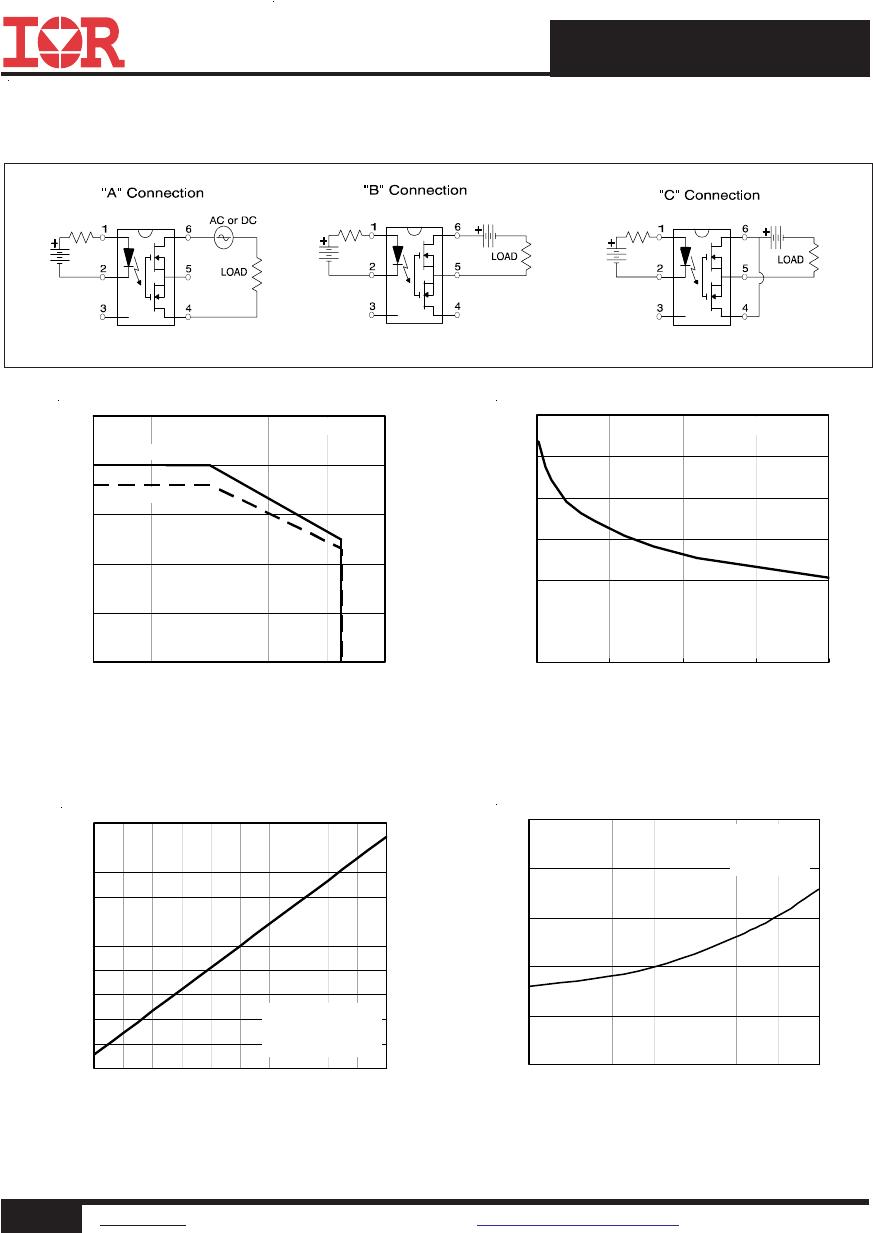
Maximum On-State Resistance @25°C, 10mA Control 100mA pulsed load, (see figs. 3 & 4)
A Connection 50 m
B Connection 25 m
C Connection 15 m
Maximum Off-State Leakage @ T
A
=+25°C, ±20V
DC
1.0 µA
Maximum Turn-On Time @T
A
=+25°C (see figure 7), for 1A, 20 V
DC
load, 10mA Control 3.0 ms
Maximum Turn-Off Time @T
A
=+25°C (see figure 7), for 1A, 20 V
DC
load, 10mA Control 0.5 ms
Typical Output Capacitance @ 20V
DC
(see figure 2) 400 pF
OUTPUT CHARACTERISTICS Limits Units
Operating Voltage Range 0 to ±20 V
(DC or AC peak)
Maximum Continuous Load Current @ 40°C, 10mA Control (see figure 1)
A Connection 4.0 A (DC or AC)
B Connection 4.5 A (DC)
C Connection 6.0 A (DC)
Maximum Pulsed Load Current @ 25°C,10mA Control (100 mS @ 10% duty cycle)
A Connection 8.0 A (DC or AC)
B Connection 9.0 A (DC)
C Connection 15.0 A (DC)
Typical Thermal Resistance (Tthja, Junction-to-Ambient)
A Connection 85.1 (
o
C/W)
B Connection 122.9 (
o
C/W)
C Connection 89.7 (
o
C/W)
Series PVN012APbF
3 www.irf.com © 2015 International Rectifier Submit Datasheet Feedback May 12, 2015
Connection Diagrams
Figure 1. Current Derating Curves* Figure 2. Typical Output Capacitance
Typical Capacitance (pF)
Max. Load Current (A)
Voltage Drop (mV)
Rd-on (Normalized to 25°
o
C)
Figure 3. Linearity Characteristics Figure 4. Typical Normalized On-Resistance
* Derating of ‘B’ and ‘C’ connections at +85°C will be 70% of that specified at +40°C and is linear from +40°C to +85°C.
0.0
1.0
2.0
3.0
4.0
5.0
0 20406080100
Ambient Temperature (°C)
I
LED
= 10mA
I
LED
= 5mA
"A" Connection
0
200
400
600
800
1000
1200
0 5 10 15 20
V
DD
Drain to Drain Voltage
"A" Connection
-250
-200
-150
-100
-50
0
50
100
150
200
250
-10-8-6-4-20246810
Load Current (A)
I
LED
= 10mA
100mS Pulsed, 25°C
"A" Connection
0
0.5
1
1.5
2
2.5
-50 -25 0 25 50 75 100 125
Ambient Temperature (°C)
"A" Connection
10mA Control
I
D
= 1A

PVN012APBF

Mfr. #:
Manufacturer:
Infineon Technologies
Description:
SSR RELAY SPST-NO 4A 0-20V
Lifecycle:
New from this manufacturer.
Delivery:
DHL FedEx Ups TNT EMS
Payment:
T/T Paypal Visa MoneyGram Western Union

Products related to this Datasheet