cui.com
date 09/16/2013 │ page 4 of 5CUI Inc │ SERIES: VLED15 │ DESCRIPTION: LED DRIVER
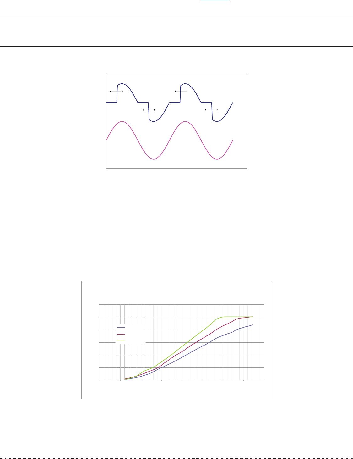
DIMMING RANGE
When operating with an incandescent dimmer, the RMS output current shall vary depending upon the
conduction angle and RMS value of the applied AC input voltage. The following graph shows the typical output
versus conduction angle at various line voltages.
The specifi ed dimming range shall be from 30 degrees through 147 degrees conduction angle. Operation
throughout this dimming range shall be monotonic and produce a smooth transition of light output in both
directions of the dimming range. At 120 Vac or 240 Vac input, the driver shall achieve full rated output
current at less than 147 degree conduction angle.
Typical Io vs Conducon Angle
0
0.2
0.4
0.6
0.8
1
1.2
0 20406080100120140160
VAC Conducon Angle (Degrees)
Output Current (A) Normalized to I Set
100V (200V)
115V (230V)
132V (264V)
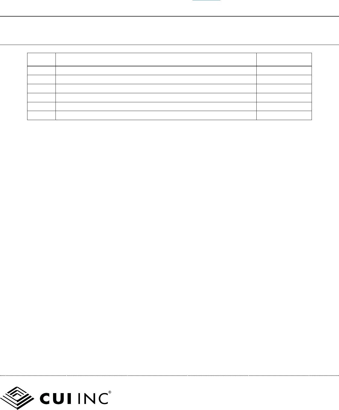
DIMMING REQUIREMENTS
Dimming of the driver shall be possible with standard triac based incandescent dimmers that chops the AC
voltage as shown below or with Electronic Low Voltage dimmers that employ reverse phase control.
During the rapid rise time of the AC voltage when the dimmer turns on, the driver shall not generate any
voltage or current oscillations and inrush current shall be controlled. During the on time of the AC input, the
driver shall regulate the output. The RMS value of the driver output current shall be proportional to the on
time of the AC input voltage. Care must be taken to assure that the minimum load requirements are met.
Multiple drivers/LEDs may be connected to the dimmer in order to meet the minimum load requirement.
Chopped AC Input to Driver
AC Wall Power
For more information, please visit the product page.