Features
■ Wirewound and Hybritron
®
elements
■ High rotational life
■ Optional 0.15 % linearity
■ Optional A/R lug
■ RoHS compliant*
■ Suitable for use under side load
■ Designed for HMI and MMI applications
■ Dual gang option
■ Servo mount option
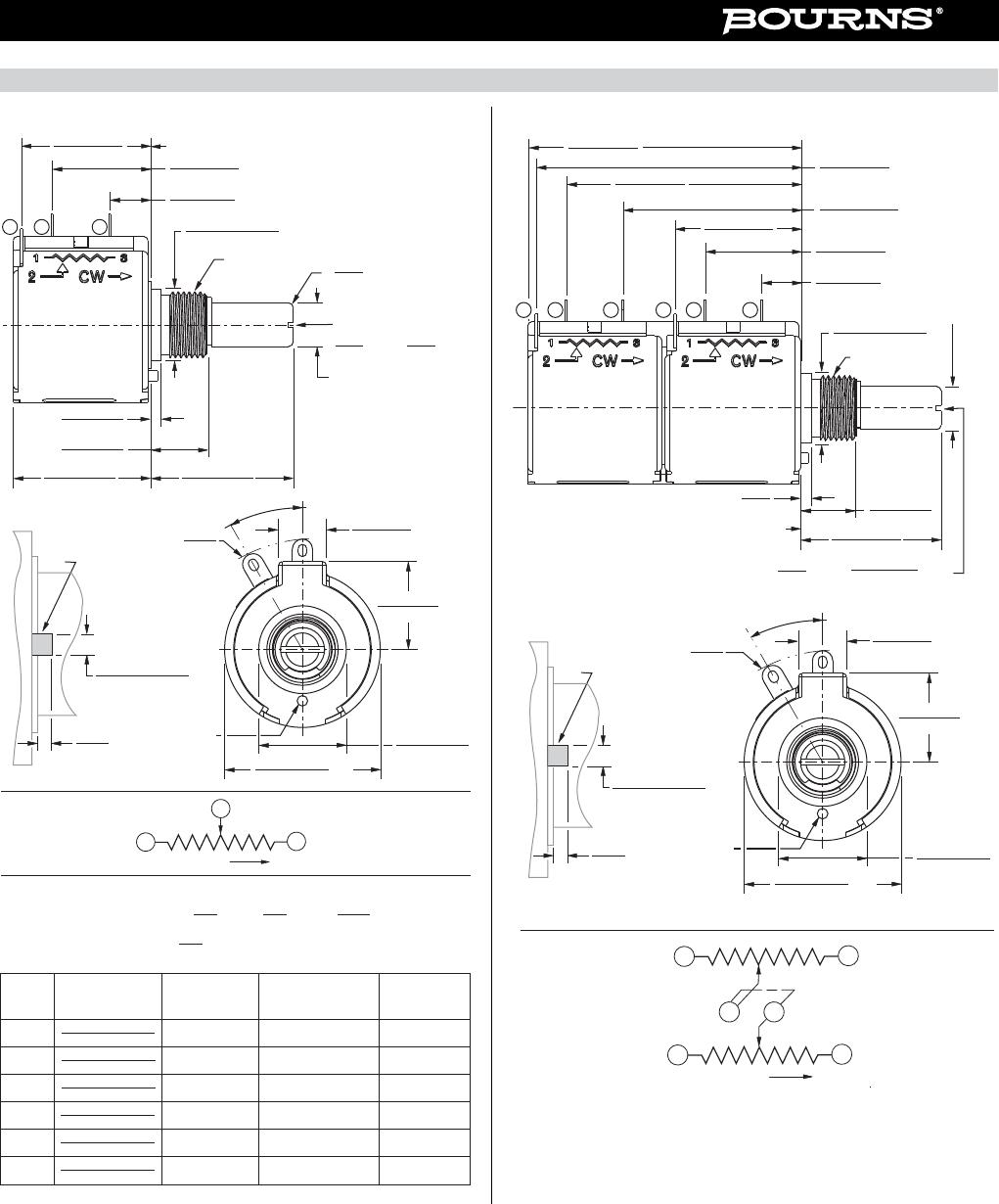
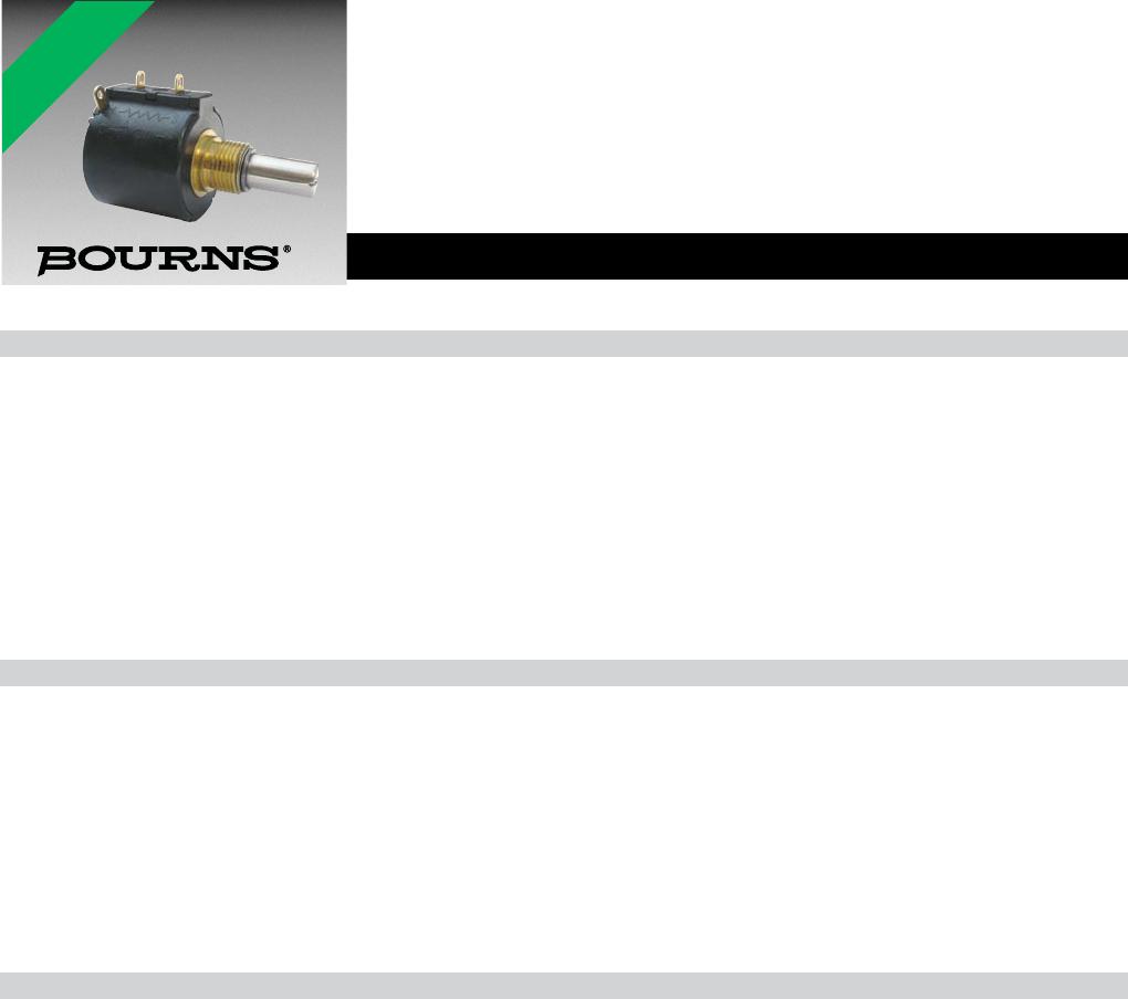
3548 - 5-Turn Precision Potentiometer
*RoHS Directive 2002/95/EC Jan. 27, 2003 including annex and RoHS Recast 2011/65/EU June 8, 2011.
Specifi cations are subject to change without notice.
The device characteristics and parameters in this data sheet can and do vary in different applications and actual device performance may vary over time.
Users should verify actual device performance in their specifi c applications.
Electrical Characteristics
1
Wirewound Element Hybritron
®
Element
Standard Resistance Range..................................................................500 to 50K ohms ....................................................1K to 10K ohms
Total Resistance Tolerance ....................................................................±3 % .......................................................................±10 %
Independent Linearity ............................................................................±0.25 % ..................................................................±0.25 %
Independent Linearity (Maximum Practical) ..........................................±0.15 % ..................................................................±0.15 %
Effective Electrical Angle .......................................................................1800 ° +10 °, -0 ° ....................................................1800 ° +10 °, -0 °
Absolute Minimum Resistance/End Voltage ..........................................1 ohm or 0.1 % maximum ......................................0.4 % maximum
(whichever is greater)
Noise/Output Smoothness ....................................................................100 ohms maximum ...............................................0.15 % maximum
Max. Wiper Current @ 5K ohms ...........................................................20 mA .....................................................................10 mA
Dielectric Withstanding Voltage (MIL-STD-202, Method 301)
Sea Level ...........................................................................................1,000 VAC minimum ..............................................1,000 VAC minimum
Insulation Resistance (500 VDC) ..........................................................1,000 megohms minimum ......................................1,000 megohms minimum
Resolution..............................................................................................See How to Order chart ........................................Essentially infi nite
Power Rating (Voltage Limited By Power Dissipation)
+70 °C ................................................................................................1.5 watts .................................................................1.5 watts
+125 °C ..............................................................................................0 watt ......................................................................0 watt
Environmental Characteristics
1
Operating Temperature Range
Dynamic .............................................................................................-40 °C to +125 °C ...................................................-40 °C to +125 °C
Static ..................................................................................................-55 °C to +125 °C ...................................................-55 °C to +125 °C
Temperature Coeffi cient (Over Static Temperature Range) ..................±50 ppm/°C ............................................................±100 ppm/°C
Temperature Cycling (5 Cycles Over Static Temperature Range) .........±2 % TR shift max. .................................................±4 % TR shift max.
Vibration (15 Gs, 10 Hz to 2 kHz)
Wiper Bounce .................................................................................... 0.1 ms max. ............................................................0.1 ms max.
Shock (100 Gs, 6 ms sawtooth)
Wiper Bounce .................................................................................... 0.1 ms max. ............................................................0.1 ms max.
Load Life (1,000 hours @ 70 °C) ...........................................................±2 % TR shift max. .................................................±5 % TR shift max.
Rotational Life
No Load ............................................................................................. 1,000,000 shaft revolutions ...................................2,500,000 shaft revolutions
Powered (MIL-PRF-12934)................................................................1,000,000 shaft revolutions ...................................2,500,000 shaft revolutions
Moisture Resistance (Mil-Std-202, Method 103) ...................................±2 % TR shift max. .................................................±5 % TR shift max.
IP Rating ................................................................................................IP 50 .......................................................................IP 50
Mechanical Characteristics
1
Mechanical Angle ...........................................................................................................................................................................................1800 ° +10 °, -0 °
Backlash .................................................................................................................................................................................................................... 1.0 ° max.
Stop Strength.......................................................................................................................................................................................53 N-cm (75 oz-in.) min.
Torque
Starting ........................................................................................................................................................................................0.5 N-cm (0.7 oz.-in.) max.
Running .......................................................................................................................................................................................0.5 N-cm (0.7 oz.-in.) max.
Clutch................................................................................................................................................................................1.0 to 4.2 N-cm (1.5 to 6.0 oz.-in.)
Mounting .......................................................................................................................................................................... 170-200 N-cm (15-18 in.-lb.) max.
Shaft Runout T.I.R. ..................................................................................................................................................................................... 0.08 mm (0.003 in.)
Lateral Runout T.I.R. ................................................................................................................................................................................... 0.13 mm (0.005 in.)
Shaft End Play T.I.R. .................................................................................................................................................................................. 0.15 mm (0.006 in.)
Shaft Radial Play T.I.R. ............................................................................................................................................................................... 0.08 mm (0.003 in.)
Pilot Diameter Runout T.I.R. ....................................................................................................................................................................... 0.08 mm (0.003 in.)
Weight
Single .................................................................................................................................................................................................... 19 gm (0.67 oz.) typ.
Dual ..................................................................................................................................................................................................... 35 gm. (1.23 oz.) typ.
Shaft Side Load (Max. Allowable)
Nickel Plated Brass Shaft w/Brass Bushing ................................................................................................................................................. 50 gmf (1.7 ozf)
Stainless Steel Shaft w/Bronze Bushing .................................................................................................................................................... 250 gmf (8.8 ozf)
Terminals .............................................................................................................................................................................................. Gold-plated solder lugs
Soldering Condition
Manual Soldering ........................................................... 96.5Sn/3.0Ag/0.5Cu solid wire or no-clean rosin cored wire, 370 °C (700 °F) max. for 3 seconds
Wave Soldering ...................................................................................96.5Sn/3.0Ag/0.5Cu solder with no-clean fl ux, 260 °C (500 °F) max. for 5 seconds
Wash processes .......................................................................................................................................................................................Not recommended
Mounting Hardware ............................................................................................. One lockwasher and one mounting nut is shipped with each potentiometer
Recommended Panel Thickness (Bushing Mount) ..................................................................................................................2.46-3.81 mm (0.097-0.150 in.)
Marking ...........................................................................................................................Manufacturer’s symbol, model number, product code and date code
Standard Packaging ...........................................................................................................................................................................Plastic trays (5 pcs./tray)
1
At room ambient: +25 °C nominal and 50 % relative humidity nominal, except as noted.
For other options, please consult factory.
*RoHS COMPLIANT